Carbon dioxide (CO2) sensor

a technology of carbon dioxide and sensors, applied in the field of carbon dioxide (co2) sensors, can solve the problems of requiring expensive detectors and light sources, and limiting the use of this type of sensor

Active Publication Date: 2016-04-19
POLESTAR TECH
View PDF6 Cites 11 Cited by
  • Summary
  • Abstract
  • Description
  • Claims
  • Application Information

AI Technical Summary

Problems solved by technology

Although widely accepted for measurements of dissolved CO2, the Severinghaus type sensor is not suitable for gas phase measurements.
Sensor drift arising from loss of electrolyte by evaporation or failure due to puncture of the sensor's Teflon membrane are among the most serious factors limiting the use of this type of sensor.
Although sensitive, the IR devices require expensive detectors and light sources, and must include sample cell heaters or water vapor filters under conditions where water condensation can occur in order to avoid interference in their readings.
Issues with correlation and / or accuracy in comparative studies against invasive blood gas analysis have raised questions about the utility of these devices, particularly when applied to adult subjects.
Studies of Severinghaus-type transcutaneous CO2 electrodes have shown better correlation with blood gas analysis (BGA) values, but there remain problems with inaccuracies arising from calibration drift due to evaporative loss of electrolyte and slow response times which introduce a time lag in readings taken with this type of sensor.
However, local heating does not appreciably reduce the two to three minute response times of CO2 electrodes which introduces a time lag in readings that can be misinterpreted as an error when compared with BGA readings especially if blood samples occurs during a period of rapid change in the arterial CO-level.
Scrubber failure, which can result from many causes, leads to black-out and hence is very dangerous to the diver.
Currently, no such CO2 sensor exists for the use of deep sea divers.

Method used


Image

  • Carbon dioxide (CO<sub>2</sub>) sensor
  • Carbon dioxide (CO<sub>2</sub>) sensor
  • Carbon dioxide (CO<sub>2</sub>) sensor

Examples


Embodiment Construction

[0026]The following detailed description presents the currently contemplated modes of carrying out the invention. The description is not to be taken in a limiting sense, but is made merely for the purpose of illustrating the general principles of the invention, since the scope of the invention is best defined by the appended claims.

[0027]As used herein, the singular forms “a,”“an,” and “the” include the plural reference unless the context clearly dictates otherwise.

[0028]Except where otherwise indicated, all numbers expressing quantities of ingredients, reaction conditions, and so forth used in the specification and claims are to be understood as being modified in all instances by the term “about.”

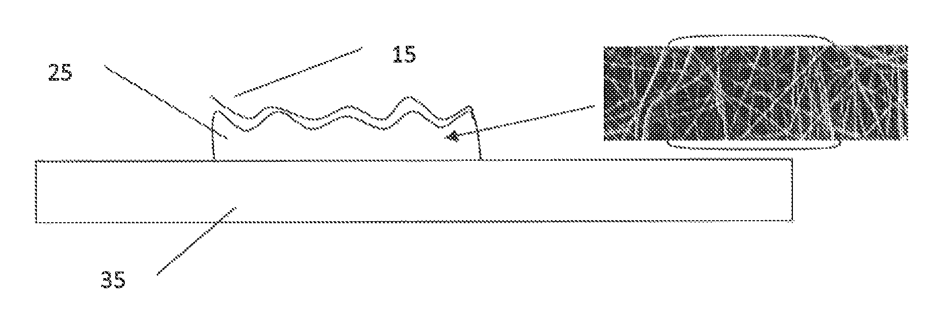
[0029]In one or more embodiments, the sensor of these teachings includes a salt of a colorimetric pH indicator (D) and lipophilic phosphonium quaternary cation (Q+) deposited on a surface of a pore structure of a porous polymer membrane, where a transparent polymer vehicle or a plasticizer...


PUM

PropertyMeasurementUnit
timeaaaaaaaaaa
flashing frequencyaaaaaaaaaa
currentaaaaaaaaaa

Abstract

A carbon dioxide detector including a sensor component, where the sensor component has a colorimetric indicator salt of a colorimetric pH indicator and a lipophilic phosphonium quaternary cation, a transparent polymer vehicle or a plasticizer not being in a mixture with the colorimetric indicator salt; and a porous memory, a porous polymer membrane in one instance, the colorimetric indicator salt being deposited on a surface of the porous polymer membrane; the colorimetric indicator salt deposited on the porous polymer membrane does not include a transparent polymer vehicle or a plasticizer, and carbon dioxide detection systems using the detector.

Description

CROSS REFERENCE TO RELATED APPLICATIONS[0001]This application claims priority to U.S. Provisional Application Ser. No. 61 / 654,219, filed on Jun. 1, 2012, entitled, “CARBON DIOXIDE (CO2) SENSOR,” which is incorporated by reference herein in its entirety for all purposes.STATEMENT REGARDING FEDERALLY SPONSORED RESEARCH OR DEVELOPMENT[0002]This invention was made partially with U.S. Government support from the U.S. Navy under contract N0463A-10-C-004, from the U.S. Army under contract W81XWH-10-C-0039. The U.S. Government has certain rights in the invention.BACKGROUND[0003]This invention relates generally to carbon dioxide (CO2) sensors.[0004]Electrochemical CO2 sensor using a Severinghaus electrode are known. Although widely accepted for measurements of dissolved CO2, the Severinghaus type sensor is not suitable for gas phase measurements. Sensor drift arising from loss of electrolyte by evaporation or failure due to puncture of the sensor's Teflon membrane are among the most serious ...

Claims


Application Information

Patent Timeline
Patent Type & Authority Patents(United States)
IPC IPC(8): A61B5/1455G01N21/80G01N31/22G01N21/78A61B5/1491
CPCG01N21/80A61B5/14551A61B5/14552G01N21/783G01N31/223A61B5/1491
Inventor KANE, JAMES A.
Owner POLESTAR TECH
Why Eureka
Try Eureka