System and method for improving the performance of a selective catalyst reduction system in a heat recovery steam generator

a technology of selective catalyst and heat recovery steam, which is applied in the direction of steam engine plants, exhaust treatment, lighting and heating apparatus, etc., can solve the problems of low steam temperature, reduced steam production, and reduced thermal efficiency of conventional gas turbines

Active Publication Date: 2017-09-14
GENERAL ELECTRIC TECH GMBH
View PDF8 Cites 6 Cited by
  • Summary
  • Abstract
  • Description
  • Claims
  • Application Information

AI Technical Summary

Benefits of technology

[0009]In an embodiment, a heat recovery steam generator is provided. The heat recovery steam generator includes a gas inlet for receiving a flow of exhaust gas from a gas turbine, a gas outlet opposite the gas inlet and configured to transport the flow of exhaust gas to atmosphere, and a sorbent injection device intermediate the gas inlet and the gas outlet, the sorbent injection device including at least one injection port configured to inject a sorbent into the flow of exhaust gas. The sorbent is configured to react with an acid gas within the flow of exhaust gas to neutralize the acid gas and inhibit the formation of salt deposits.

Problems solved by technology

Conventional gas turbines, however, operate with reduced thermal efficiency due to the high exit temperatures of the exhaust gas stream and the resulting thermal loss.
While existing SCR systems are generally effective in reducing emissions levels to comply with stringent standards, they can contribute to the formation of deposits on heat transfer surfaces within the heat recovery steam generator.
These deposits are a common cause of reduced steam production, low steam temperatures, and degraded gas turbine performance, which may contribute to reduced electricity production and lost revenue.
In particular, over time, fouling can bridge the gap between adjacent tube fins or other heat-transfer surfaces, further disrupting heat transfer and increasing gas-side pressure drop.
In cases where heat recovery steam generator performance is severely compromised, the entire plant may require an extended forced outage to remove deposits from heat-transfer surfaces, or even replace an entire boiler module.

Method used


Image

  • System and method for improving the performance of a selective catalyst reduction system in a heat recovery steam generator
  • System and method for improving the performance of a selective catalyst reduction system in a heat recovery steam generator
  • System and method for improving the performance of a selective catalyst reduction system in a heat recovery steam generator

Examples


Embodiment Construction

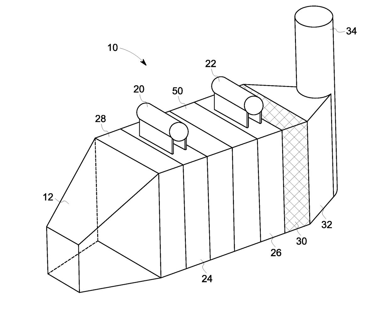
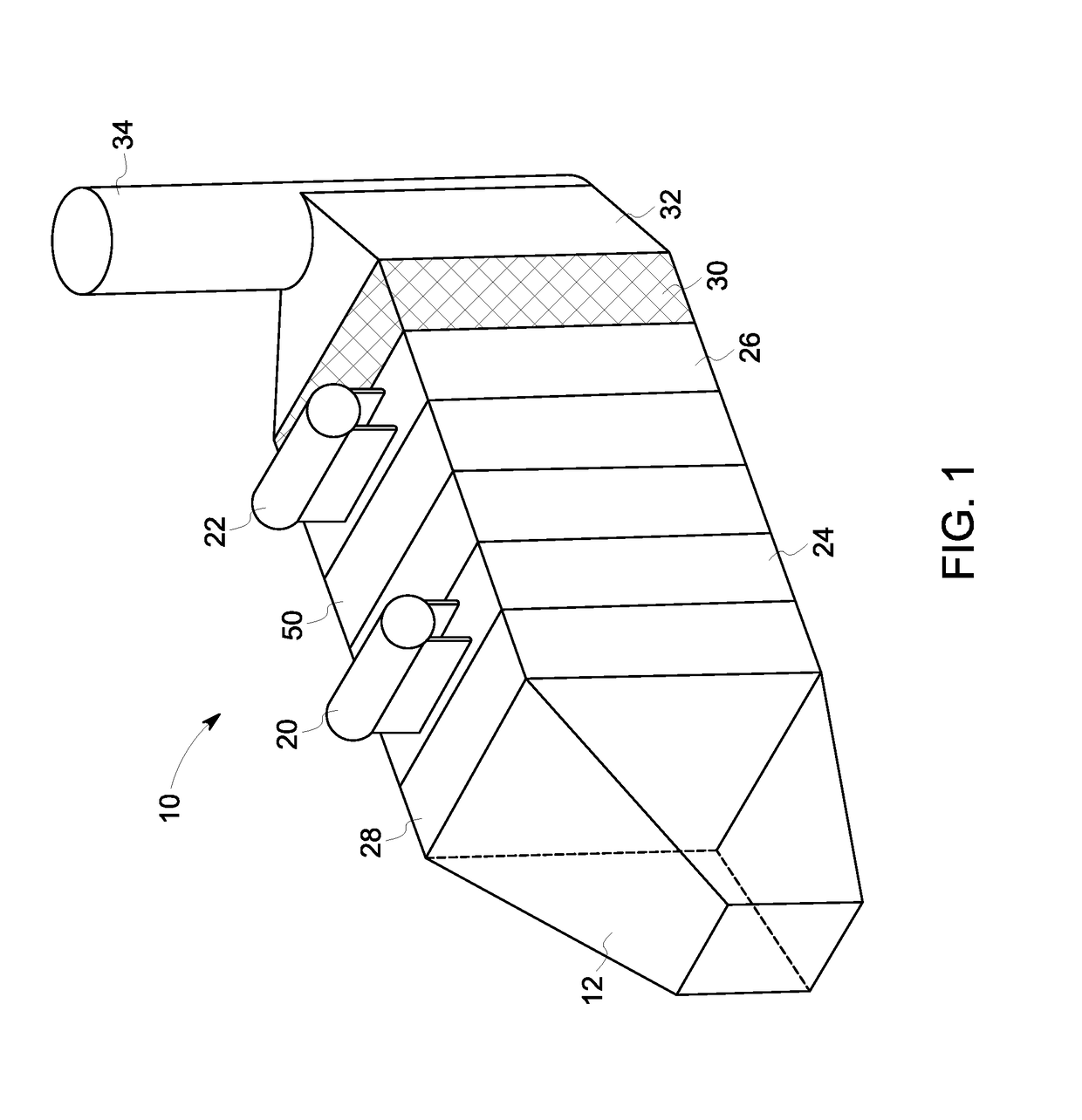
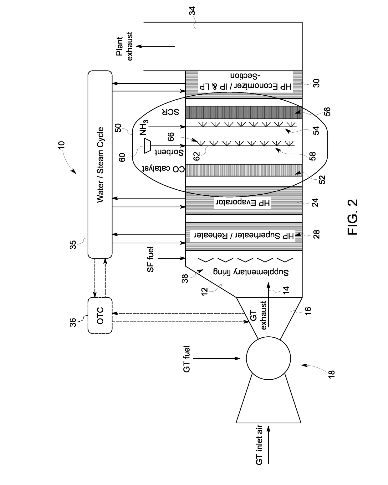
[0016]Reference will be made below in detail to exemplary embodiments of the invention, examples of which are illustrated in the accompanying drawings. Wherever possible, the same reference characters used throughout the drawings refer to the same or like parts. While embodiments of the invention are suitable for use in a heat recovery steam generator of a combined cycle or cogeneration power plant employing gas turbines, embodiments of the invention may also be applicable for use in other gas turbine applications where sulfur oxides or other acidic gases are desired to be removed from flue gas exiting the gas turbines.

[0017]As used herein, “upstream” and “downstream” refer to the flow direction of an exhaust gas from the gas turbine (i.e., exhaust gas flows from an upstream end of the heat recovery steam generator to a downstream end of the heat recovery steam generator). As used herein, “gas turbine” means a turbine driven by expanding hot gases produced by burning non-coal fuel s...


PUM

PropertyMeasurementUnit
particle sizeaaaaaaaaaa

Abstract

A heat recovery steam generator includes a gas inlet for receiving a flow of exhaust gas from a gas turbine, a gas outlet opposite the gas inlet and configured to transport the flow of exhaust gas to atmosphere, and a sorbent injection device intermediate the gas inlet and the gas outlet, the sorbent injection device including at least one injection port configured to inject a sorbent into the flow of exhaust gas. The sorbent is configured to react with an acid gas within the flow of exhaust gas to neutralize the acid gas and inhibit the formation of salt deposits.

Description

BACKGROUND[0001]Technical Field[0002]Embodiments of the invention relate generally to power generation systems and, more particularly, to a system and method for improving the performance of a selective catalyst reduction system in a heat recovery steam generator.[0003]Discussion of Art[0004]Gas turbines have been widely used to provide electric power, usually as a standby for both peak power and reserve power requirements in the utility industry. Gas turbines are preferred because of their rapid starting capability and low capital cost. Conventional gas turbines, however, operate with reduced thermal efficiency due to the high exit temperatures of the exhaust gas stream and the resulting thermal loss. Therefore, a gas turbine is often combined with a heat recovery steam generator to improve overall system efficiency.[0005]As is known in the art, a heat recovery steam generator generates steam utilizing the energy in the exhaust from the gas turbine. In a cogeneration mode, steam pr...

Claims


Application Information

Patent Timeline
Patent Type & Authority Applications(United States)
IPC IPC(8): B01D53/92B01D53/34B01D53/50F01K23/10B01D53/83
CPCB01D53/92F01K23/10B01D53/83B01D53/508B01D2258/01B01D2252/102B01D2251/602B01D2251/604B01D2251/606B01D53/343Y02E20/16F01N3/206F01N3/2066F01N5/02F23J15/003F01N2570/04F01N2590/10F01N2610/02F23J2219/10Y02T10/12
Inventor NILSSON, JOHN MARTINBERNERO, STEFANO
Owner GENERAL ELECTRIC TECH GMBH
Why Eureka
Try Eureka