Optical film

a technology of optical film and polarizing element, applied in the field of optical film, can solve the problems of reducing the efficiency of light utilization and brightness, and achieve the effects of reducing the degree of aggregation of dye molecules, promoting formation of nematic lyotropic liquid crystal phase, and increasing solubility

Active Publication Date: 2016-04-19
LG CHEM LTD
View PDF22 Cites 1 Cited by
  • Summary
  • Abstract
  • Description
  • Claims
  • Application Information

AI Technical Summary

Benefits of technology

[0010]In one embodiment, the optical film may be used as a brightness enhancement film. The term “brightness enhancement film” as used herein may refer to a functional film capable of enhancing the efficiency of light utilization by selectively transmitting or selectively reflecting incident light.
[0065]In such a disposition structure, the anisotropic layer of the reflective polarizing plate or the optical film may transmit some of light emitted from a light source 84, for example, light having a polarized axis in a direction parallel to the optical absorption axis of the upper polarizing plate 82, and send the light toward the polarizer, and the other light, for example, light having a polarized axis in a direction parallel to the optical transmission axis of the upper polarizing plate 82, may be reflected again toward the light source 84. The reflected light may be reflected and sent upwards. Also, the polarization characteristics of the reflected light are changed while the reflected light is re-reflected. Then, the reflected light may be incident again to the reflective polarizing plate 83, thereby improving the brightness characteristics of the display device.

Problems solved by technology

In this process, a considerable amount of the light emitted from the light source is absorbed by a polarizing plate attached to a liquid crystal panel, resulting in decreases in efficiency of light utilization and brightness.

Method used


Image

  • Optical film
  • Optical film
  • Optical film

Examples


example 1

[0074]Preparation of Lyotropic Liquid Crystal Composition (Coating Solution)

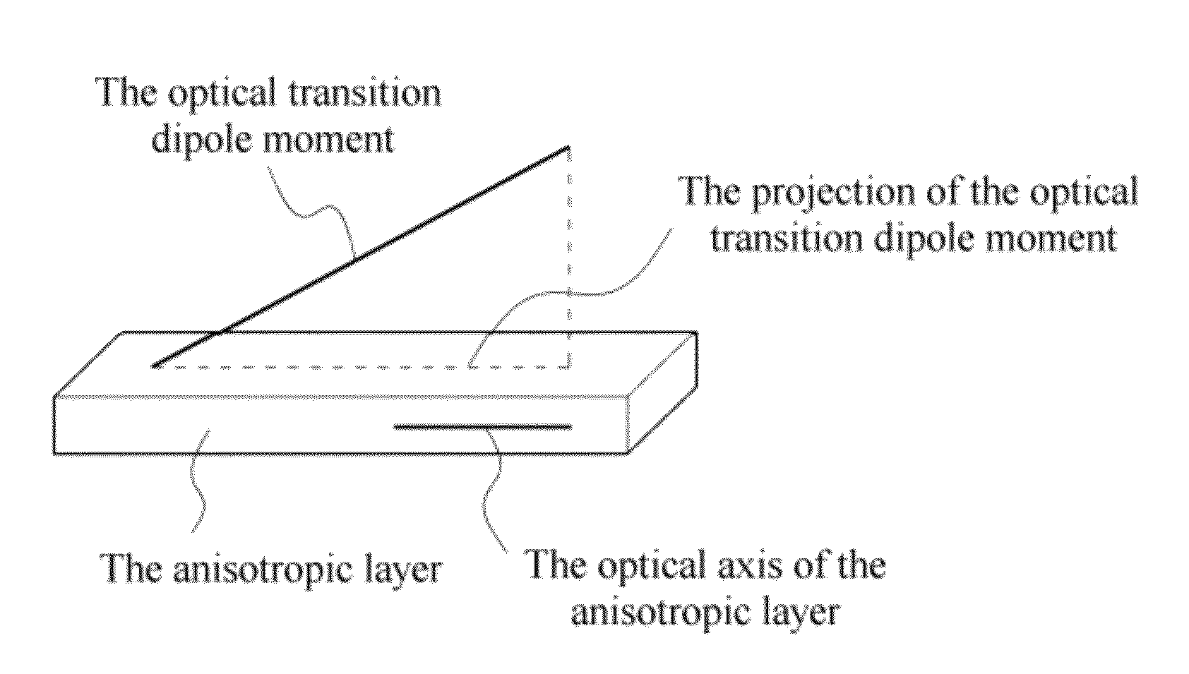
[0075]A lyotropic liquid crystal composition was prepared using a dichroic dye, which was prepared by replacing the cations in the dye known as Direct Yellow 12 in the art from Na+ to Li+, as a dichroic dye capable of forming a stable lyotropic liquid crystal phase. The minimum value of the refractive index anisotropy of the dichroic dye, in which cations were replaced with Li+, i.e., the minimum value of the absolute value of the difference between the refractive index with respect to light that has wavelength within the range of visible light and that has polarized axis in a direction parallel to an optical transition dipole moment of an anisotropically absorbing fragment of the dichroic dye and the refractive index with respect to light that has wavelength within the range of visible light and that has polarized axis in a direction perpendicular to an optical transition dipole moment of an anisotropically...

example 2

[0080]A reflective polarizing plate was prepared in the same manner as in Example 1, except that the anisotropic layer formed on the TAC film was attached to the polyvinyl alcohol polarizer, and the brightness characteristics were evaluated in the same manner as in Example 1. The results are shown in FIG. 11.


PUM

PropertyMeasurementUnit
absorption wavelengthaaaaaaaaaa
maximum absorption wavelengthaaaaaaaaaa

Abstract

An optical film, a reflective polarizing plate and a display device are provided. For example, the optical film may be used in the reflective polarizing plate which may enhance the efficiency of light utilization of a display device such as a liquid crystal display device and improve the brightness.

Description

CROSS-REFERENCE TO RELATED APPLICATION[0001]This application is a continuation application of International Application PCT / KR2011 / 005469, with an international filing date of Jul. 25, 2011, which claims priority to and the benefit of Korean Patent Application No. 2010-0071560, filed Jul. 23, 2010, the disclosure of which is incorporated herein by reference in its entirety.BACKGROUND[0002]1. Field of the Invention[0003]The present invention relates to an optical film, a reflective polarizing plate and a display device.[0004]2. Discussion of Related Art[0005]Brightness is a physical property representing brightness per unit area of a light source and a factor that determines the performance of a display device. A representative way to enhance the brightness of a display device includes a method of increasing the intensity of a light source and a method using an optical film for improving the brightness.[0006]For example, a liquid crystal display device (LCD) displays an image by tran...

Claims


Application Information

Patent Timeline
Patent Type & Authority Patents(United States)
IPC IPC(8): G02B5/30G02F1/1335C09K19/52
CPCG02B5/3016G02F1/133536B32B2457/202C09K19/52G02B5/30G02F1/1335G02F1/13363
Inventor CHANG, JUN WONLEE, DAE HEEPARK, MOON SOOBELYAEV, SERGEY
Owner LG CHEM LTD
Why Eureka
Try Eureka