
Method and apparatus for maintaining communications connections over a distributed wireless network

a distributed wireless network and communication connection technology, applied in electrical devices, wireless communication services, network topologies, etc., can solve the problems of loss of connection, inability to maintain communication connections, so as to and increase the potential communication bandwidth

Active Publication Date: 2016-04-19
IBM CORP
View PDF17 Cites 7 Cited by
  • Summary
  • Abstract
  • Description
  • Claims
  • Application Information

AI Technical Summary

Benefits of technology

The patent describes a technique to increase the bandwidth and coverage area of a wireless network by using multiple small servers with small coverage areas. This approach provides better bandwidth and reduces power consumption for mobile clients. The technique does not require any changes to current clients and can support existing devices. Overall, this approach offers a cost-effective and efficient way to build and maintain a wireless network.

Problems solved by technology

This problem of losing of a connection as a mobile device moves out of range is well known in the cell phone industry, wherein certain special protocols exist to hand off a connection from one cell phone tower to another as a cell phone moves out of range of the tower with which the connection was originally made.
In the case of an IEEE 802.11 protocol and certain similar protocols, the range of the transceiver station is typically much shorter, and hence the restriction on mobility is potentially more severe.
In the first place, dropped connections are an annoyance, even if they don't happen often enough to make communications impossible or impractical.
Secondly, while digital computing devices using relatively short range IEEE 802.11 or similar wireless connections are often operated in a stationary manner, there are not always stationary, and it is sometimes desirable to maintain the connection while the digital computing device is moving.
But even more significantly, extending the range of wireless transceiver stations to reduce the frequency of dropped connections has unwanted side-effects.
These circumstances can limit the bandwidth supported by the network, because each wireless transceiver station must support a large area, i.e., one having many devices within it.

Method used


Image

  • Method and apparatus for maintaining communications connections over a distributed wireless network
  • Method and apparatus for maintaining communications connections over a distributed wireless network
  • Method and apparatus for maintaining communications connections over a distributed wireless network

Examples


Embodiment Construction

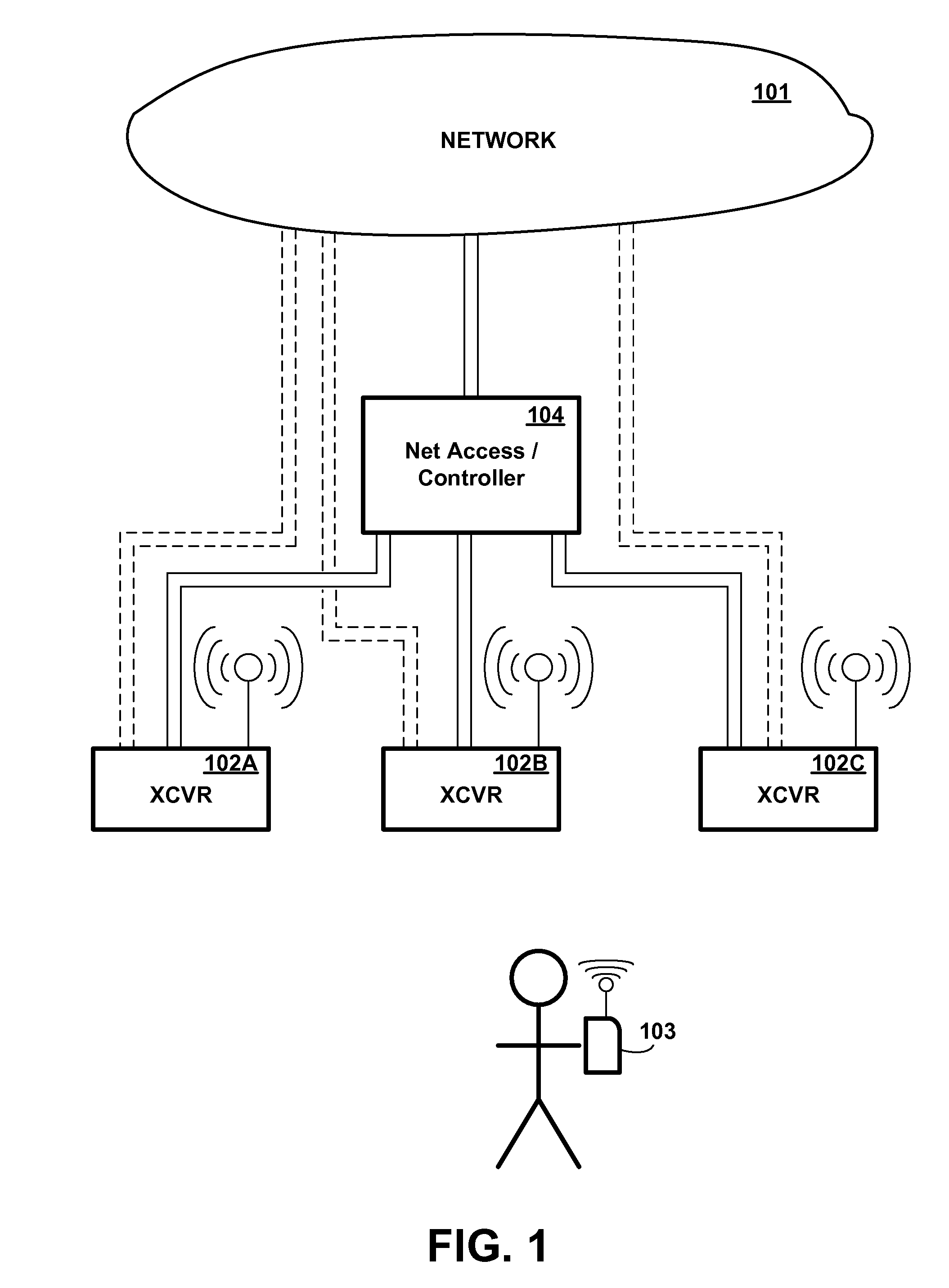
[0024]Referring to the Drawing, wherein like numbers denote like parts throughout the several views, FIG. 1 is a high-level illustration of an exemplary network environment, showing some of the major components involved in a system which automatically maintains a network connection with a mobile wireless device even as the mobile wireless device moves out of range of a wireless transceiver station, in accordance with the preferred embodiment of the present invention. As shown in FIG. 1, a network 101 is coupled to a network access device 104, which may also function as a controller, which is in turn coupled to multiple wireless transceiver stations 102A-C (herein generically referred to as feature 102), each having a different respective physical location. Although three transceiver stations are shown for illustrative purposes in FIG. 1, it will be understood that the number of stations may vary, and would typically be larger. Mobile wireless device 103 communicates with one or more...


PUM


Abstract

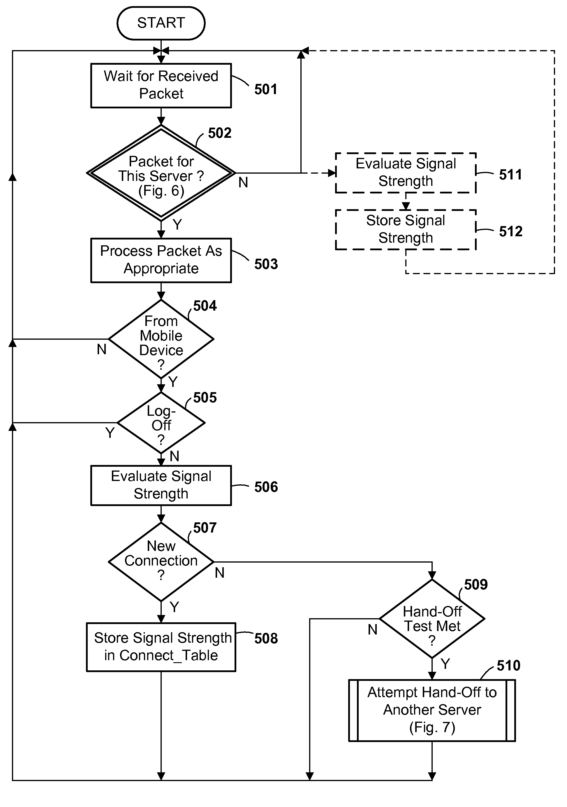
A mobile wireless device connects to a network of multiple wireless transceiver stations using a protocol in which a connection is established with a particular transceiver station. If the mobile device moves out of range of the original station, the connection is passed to another station, which then impersonates the original station, without dropping the connection. Preferably, the original station provides a virtual Media Access Control (MAC) address to identify itself when the connection is established, and this virtual MAC address is passed to any successor station. Preferably, the station monitors signal strength and automatically passes the connection by polling its neighbors upon determining that signal strength is getting weak.

Description

FIELD OF THE INVENTION[0001]The present invention relates to the use of wireless communications networks, and in particular to the maintenance of a wireless communications connection between a distributed network of servers and a client under circumstances wherein the relative signal strength of the client changes, e.g., where the client is mobile.BACKGROUND OF THE INVENTION[0002]In the latter half of the twentieth century, there began a phenomenon known as the information revolution. While the information revolution is a historical development broader in scope than any one event or machine, no single device has come to represent the information revolution more than the digital electronic computer. The development of computer systems has surely been a revolution. Each year, computer systems grow faster, store more data, and provide more applications to their users. At the same time, the cost of computing resources has consistently declined, so that information which was too expensiv...

Claims


Application Information

Patent Timeline
Patent Type & Authority Patents(United States)
IPC IPC(8): H04W4/00H04W36/30H04W40/08H04W8/26H04W84/12
CPCH04W36/30H04W40/08H04W8/26H04W84/12H04W36/0016H04W36/302
Inventor MCMANUS, BRIAN D.THORSTENSEN, ANDREW T.
Owner IBM CORP
Learn More