Flywheel energy system

a technology of energy system and flywheel, which is applied in the direction of electric storage system, bearing unit rigid support, mechanical apparatus, etc., can solve the problems of limited effectiveness of lead acid batteries for large-scale applications, limited effectiveness of li-ion batteries as suitable energy-storage technology, and limited effectiveness of metal-air batteries

Active Publication Date: 2016-04-26
BC NEW ENERGY (TIANJIN) CO LTD
View PDF183 Cites 22 Cited by
  • Summary
  • Abstract
  • Description
  • Claims
  • Application Information

AI Technical Summary

Benefits of technology

[0016]c) a magnetic bearing assembly juxtaposed between said end face and said rotor, said magnetic bearing assembly having at least one permanent magnet mounted on one of the first housing and said rotor to attract said rotor axially upwardly towards said end face to at least partially support the weight of said flywheel;d) a first mechanical bearing assembly acting between said first housing and said rotor to provide radial positioning of said rotor and to limit at least upward axial movement of the rotor in relation to said end face such that a minimum clearance gap is defined between said end face and the rotor; ande) a second mechanical bearing assembly spaced from said first bearing assembly along said drive shaft and acting between said first housing and said rotor to provide radial positioning of said rotor, said second mechanical bearing assembly permitting relative axial movement between said shaft and said housing.
[0020]c) a magnetic bearing assembly juxtaposed between said end face and said rotor, said magnetic bearing assembly having at least one annular permanent magnet mounted on one of the first housing and said rotor to attract said rotor axially upwardly towards said end face to at least partially support the weight of said flywheel; and,d) at least one mechanical bearing assembly mounted within the first housing about the drive shaft to provide radial positioning of said rotor and to limit at least upward axial movement of the rotor portion in relation to said lower face such that a minimum clearance gap is defined between said end face and said rotor, said end face and said rotor extending radially beyond said permanent magnet to establish a flux path between said housing and said rotor.

Problems solved by technology

Some of these challenges include managing intermittent renewable energy generation, electricity load shifting, black-start capabilities, managing electricity price fluctuations, and back-up power supply.
However, the effectiveness of lead acid batteries for large-scale applications is limited by the very short life cycle of such batteries, and the variable discharge rate.
The effectiveness of Li-ion batteries as suitable energy-storage technology is, however, limited by the high cost associated with the manufacture of such batteries, and by security concerns associated with large-scale implementations of Li-ion batteries.
However, the effectiveness of Metal-Air batteries is limited by the very short life cycle and low efficiencies (e.g., approximately 50%) of such batteries.
NaS batteries have high energy density but require high operating temperatures and have a relatively short life span.
However, it is not feasible to implement ECs on large-scale projects due to their high cost and low energy density.
The main drawbacks associated with pumped hydro are the unique site requirements and the large upfront capital costs.
A CAES has similar wide-scale use limitations as pumped hydro: the site locations and large upfront capital costs.
Traditional flywheel designs limit their use to the above mentioned short duration applications due to high electrical parasitic losses associated with electromagnetic bearing systems.
Such a flywheel energy storage system also has multiple mechanical bearing assemblies which each provide radial support for the flywheel rotor portion, but do not axially restrain the flywheel rotor portion.
Such systems are relatively complex and absorb significant power while in operation thus limiting their use to short duration applications.
Repulsive magnetic forces generated from permanent magnets are known to degenerate over time; and accordingly there is the possibility of mechanical failure of the device.
The magnetic path resulting from the structure shown in Hearn is relatively dispersed, which, together with the mechanical bearing arrangement disclosed, provides a relatively inefficient support system.

Method used


Image

  • Flywheel energy system
  • Flywheel energy system
  • Flywheel energy system

Examples


Embodiment Construction

[0040]Although the invention has been described with reference to certain specific embodiments, various modifications thereof will be apparent to those skilled in the art without departing from the spirit and scope of the invention as outlined in the claims appended hereto. The entire disclosures of all references recited above are incorporated herein by reference.

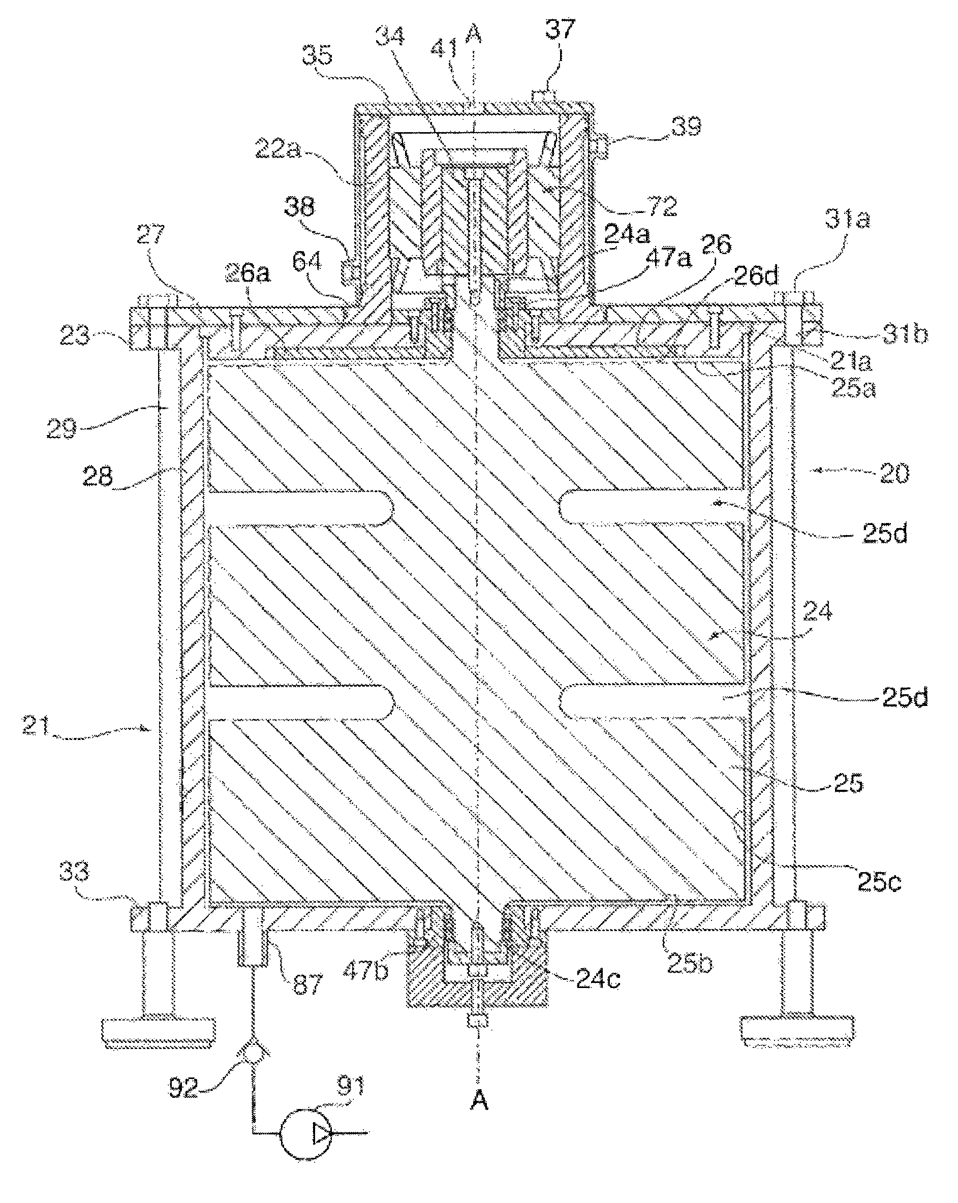
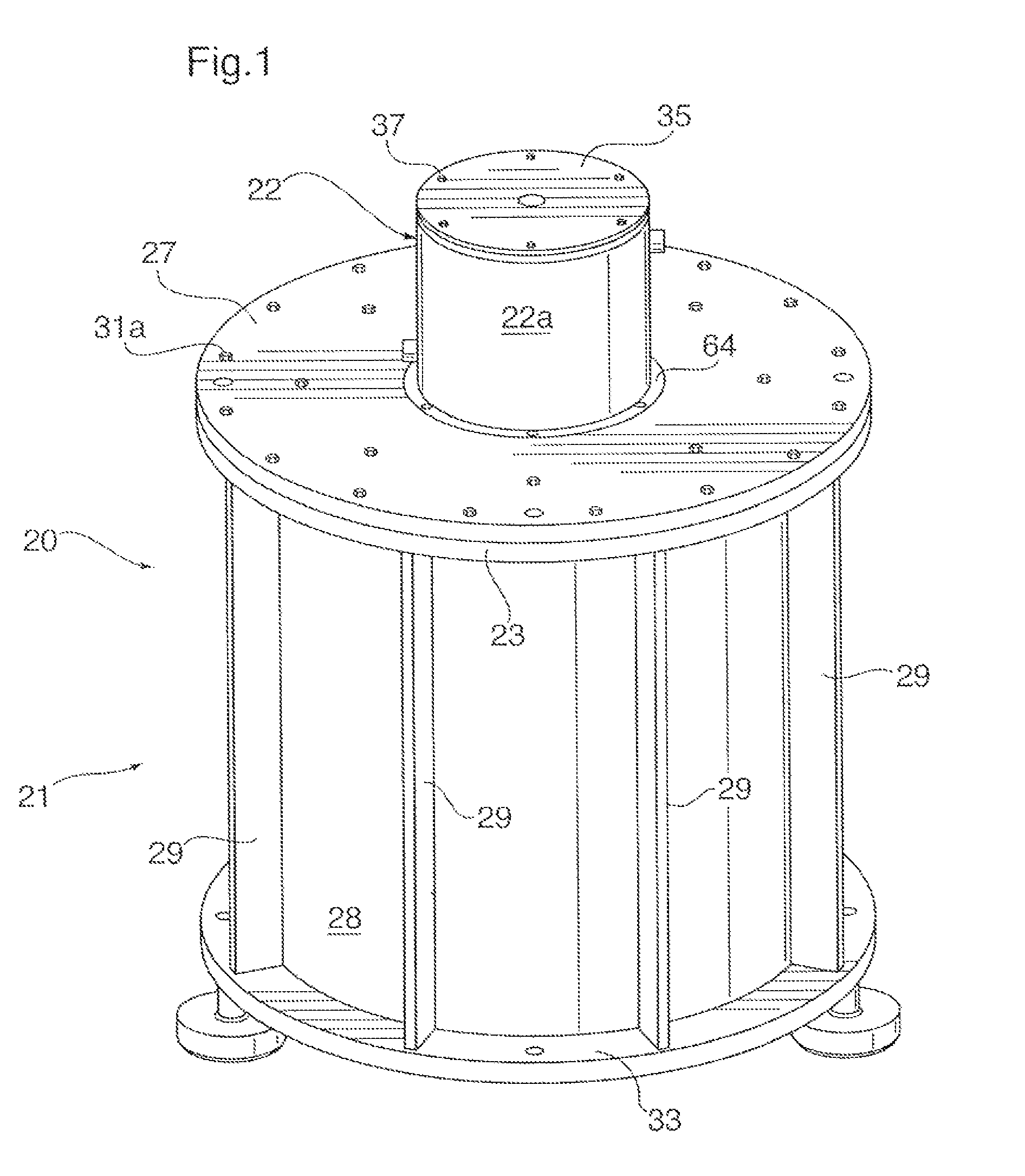
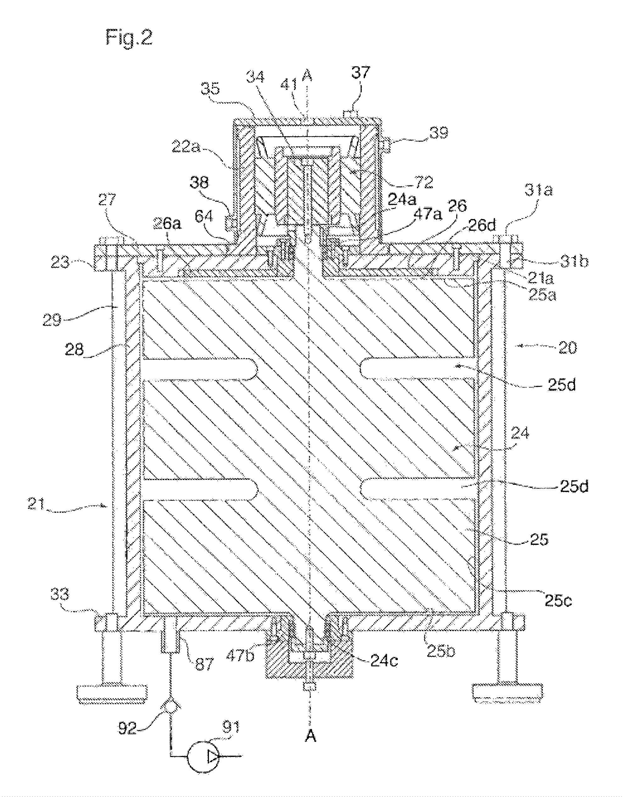
[0041]FIG. 1 is a perspective view of an energy storage system 20 that is constructed as a modular system having two major components: a first housing 21 containing a flywheel (not visible in FIG. 1) rotatably mounted therein as will be described more fully below, and a second housing 22 releasably mounted atop the first housing 21. The second housing 22 contains a motor / generator (not visible in FIG. 1) coupled to the flywheel to either drive the flywheel or be driven by the flywheel, upon operation of the system in a manner that will become more apparent as description unfolds.

[0042]As best seen in FIG. 1, the first hous...


PUM


Abstract

An energy storage system comprises a housing and a flywheel having a drive shaft portion attached to a cylindrical ferromagnetic rotor portion. The drive shaft portion defines a substantially vertical axis about which the rotor portion is mounted for rotation. A magnetic bearing assembly comprised of an annular permanent magnet having no electromagnetic components is mounted on the housing in stationary centered relation about the vertical axis above the rotor portion so as to attract the rotor portion axially upwardly towards a lower face of permanent magnet, thereby supporting a significantly high portion of the weight of the flywheel. At least one low friction mechanical bearing assembly is mounted within the housing about the drive shaft portion to provide radial positioning of the rotor portion and to limit at least upward axial movement of the rotor portion in relation to the lower face. The annular permanent magnet overlies a portion of the end face of the rotor with the balance providing a return path for magnetic flux.

Description

CROSS REFERENCE TO RELATED APPLICATIONS[0001]This application claims priority from U.S. Provisional Application No. 61 / 352,810 filed on Jun. 8, 2010, the contents of which are incorporated herein by reference.FIELD OF THE INVENTION[0002]The present invention relates to energy storage systems, and more specifically to energy storage systems capable of storing electrical energy as kinetic energy of a rotating flywheel, for release of the stored kinetic energy as electrical energy when required.DESCRIPTION OF THE PRIOR ART[0003]Large-scale energy storage has the potential to solve many challenges related to modernizing electrical power distribution. Some of these challenges include managing intermittent renewable energy generation, electricity load shifting, black-start capabilities, managing electricity price fluctuations, and back-up power supply.[0004]Currently, there are several large-scale energy storage technologies that attempt to address the challenges facing the energy storage...

Claims


Application Information

Patent Timeline
Patent Type & Authority Patents(United States)
IPC IPC(8): H02J3/38F16F15/315F16C39/06H02K9/19H02K7/09H02K7/02H02K5/10F16C32/04
CPCH02K7/025F16C39/063F16F15/3156F16C32/0417F16C2361/55F16F2222/06Y02E60/16Y10T307/718F16C35/077F16C19/163F16C19/543F16C23/08F16C19/546H02J15/007F16F15/315F16C32/04F16C39/06H02K7/02H02J3/30H02K7/09
Inventor VELTRI, JEFFREY ALLAN
Owner BC NEW ENERGY (TIANJIN) CO LTD
Why Eureka
Try Eureka