Mass analysis device and mass separation device

a mass analysis and separation device technology, applied in the direction of separation process, particle separator tube details, instruments, etc., can solve the problems of ion trapping type devices, however, that require somewhat complicated operation and are not suitable at least for fast real time measuremen

Active Publication Date: 2016-05-03
SANO YOSHINORI
View PDF14 Cites 2 Cited by
  • Summary
  • Abstract
  • Description
  • Claims
  • Application Information

AI Technical Summary

Benefits of technology

[0035]In the mass spectrometer of the present invention, said crude ions are introduced from said ion source into said separation space at said predetermined acceleration voltage. Then, each ion travels in said incident direction by inertia, and besides they are displaced in said y-direction by the force received from said one-dimensional high-frequency electric field which acts in the direction (said y-direction) crossing said incident direction. This displacement differs from the uniformly accelerated motion in a static electric field, and its magnitude is inversely proportional to the mass-to-charge ratio of the ion. Though this magnitude also varies depending on a phase at which said one-dimensional high-frequency electric field begins to act on the ion, it is kept constant if the phase is held constant. Therefore, when said crude ions are introduced into said separation space as a pulse synchronized with the phase of said one-dimensional high-frequency electric field, the ionic species having different mass-to-charge ratios with each other travel on different paths with each other, and are separated spacially (see FIG. 6 described later). On the other hand, said ion detection unit detects ions which come to the predetermined position in the y-direction on said exit plane accordingly. The position of the ion in the y-direction on said exit plane corresponds to the displacement magnitude which occurs during the travel in said separation space.
[0036]As above, the mass separation in said mass analyzer is performed based on the difference in the mass-to-charge ratio itself, through the above displacement caused by said one-dimensional high-frequency electric field. The motion of the ion in the extracted direction is not concerned to this displacement. Consequently, this mass separation is in principle less affected by the fluctuation at the initial state of said crude ions before extraction.
[0037]In practice, however, the following problem might occur. Said crude ions extracted by said acceleration voltage U have kinetic energies in the extracted direction. These kinetic energies have the standard value zieU, but are distributed around it with an extent according to the fluctuation at the initial state. Hence, the velocities of the ions in the extracted direction have the standard value (2zieU / m)1 / 2 but are distributed around it with an extent. Consequently, the times needed for the ions to arrive at the end of said separation space (the stay times that the ions spend in said separation space) have an extent even among the ions of the same mass-to-charge ratio. If this extent of the stay times brings about some extent of the displacement magnitudes of the ions in the y-direction on said exit plane, the mass resolving power of the spectrometer is restricted by the fluctuation at the initial state as a result.
[0038]The present inventor found that the above problem can be solved based on the following fact, and completed the present invention. Since the impulse which acts on an ion from the high-frequency electric field becomes 0 for one period, the rate of the displacement becomes 0 at the time when the ion has received the action for n periods. According to this fact, either of the following two is used in the mass spectrometer of the present invention. One is that said measured ionic species exits from said separation space, when it has received the action of said one-dimensional high-frequency electric field for n periods or for the substantially same time as it after the incidence into said separation space. The other is that said measured ionic species exits from said separation space, after it has received the action of said one-dimensional high-frequency electric field for n periods, within a succeeding off-time in which the electric field strength is 0.
[0039]In the former case, we pay attention to the fact that around the time when n periods have passed, there exist a time domain in which the rate of the above displacement is small. In this time domain the extent of the stay times brings about little extent of the displacement magnitudes. Consequently, if all ions of said measured ionic species exsit from said separation space within this time domain, and have received the action of said one-dimensional high-frequency electric field for n periods or for the substantially same time as it, the displacement magnitudes of said measured ionic species on said exit plane are slightly affected by the extent of its stay times.
[0040]In the latter case, the displacement becomes in a halting state at the time when n periods have passed, and this halting state is kept throughout the off-time. Hence, the extent of the stay times brings about no extent of the displacement magnitudes. Consequently, if all ions of said measured ionic species exsit from said separation space within the off-time, the displacement magnitudes of said measured ionic species on said exit plane are not affected by the extent of its stay times.

Problems solved by technology

These ion trapping type devices, however, require somewhat complicated operation for one analysis.
Moreover, since the analysis becomes intermittent, it is not suitable at least for fast real time measurement.

Method used


Image

  • Mass analysis device and mass separation device
  • Mass analysis device and mass separation device
  • Mass analysis device and mass separation device

Examples


embodiment 1

[0080]In embodiment 1, we describe an example of the mass spectrometer of the present invention which is described in claims 1-3 and 7-10. Here, we describe mainly the usually best case, namely, the case of n=1 that the measured ionic species exits from the separation space having received the action of the one-dimensional high-frequency electric field for one period or for the substantially same time as it. When necessary for description, we use mainly a rectangular wave high-frequency electric field as an example of the one-dimensional high-frequency electric field. We also describe the mass separator of the present invention described in claim 11.

[0081]

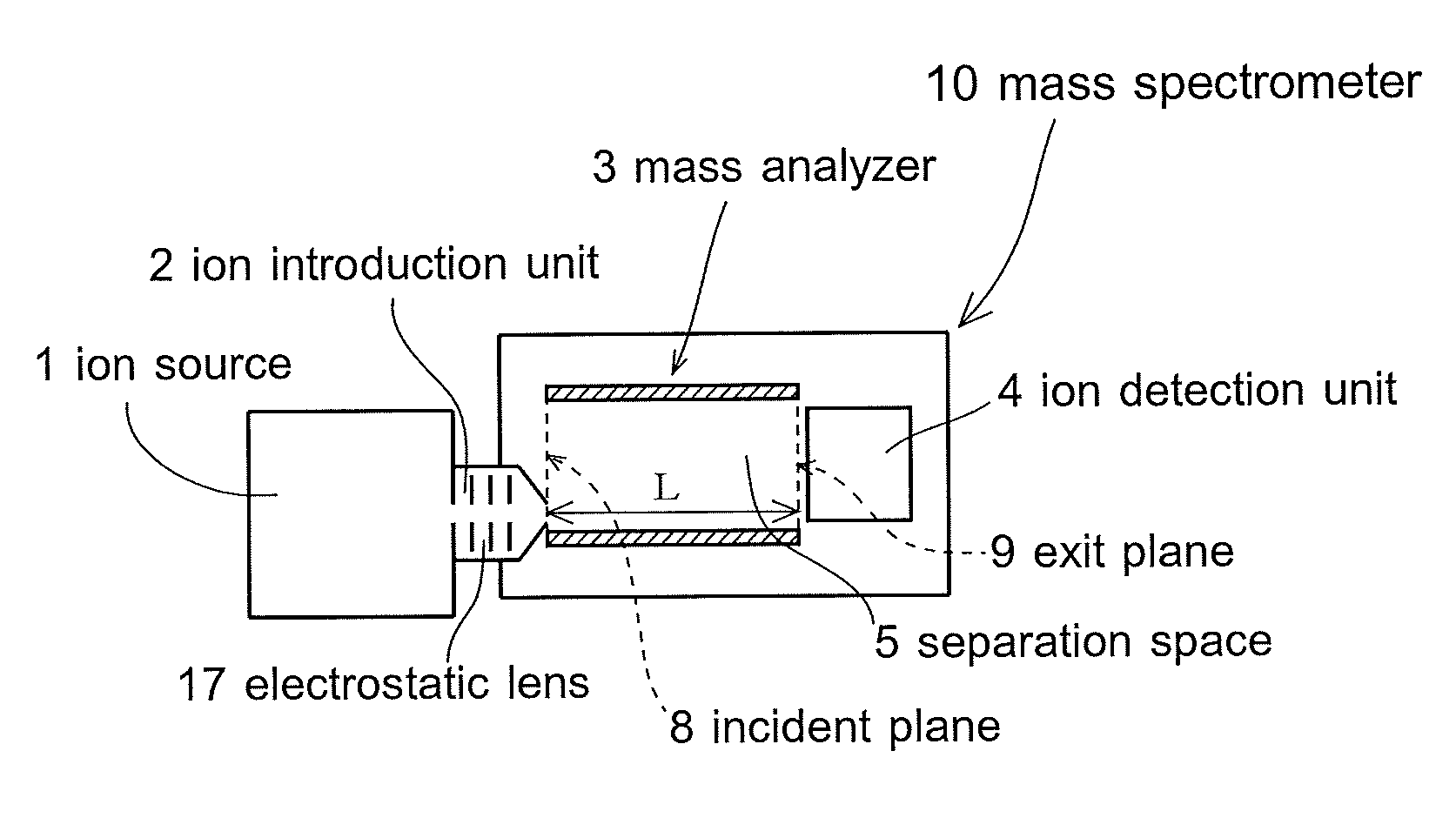
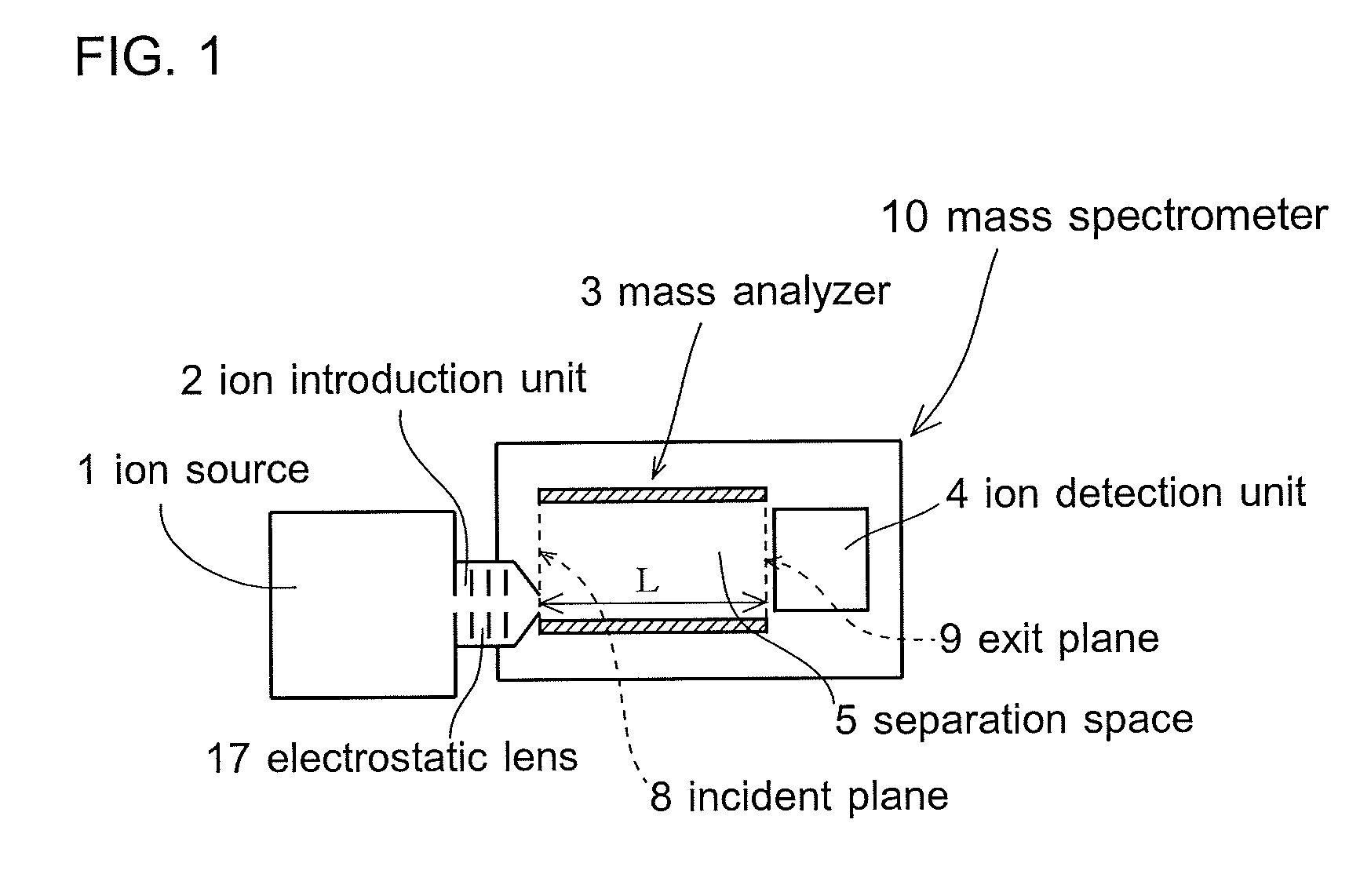
[0082]FIG. 1 is a schematic drawing showing the configuration of a mass spectrometer 10. The spectrometer 10 consists of an ion source 1, an ion introduction unit 2, a mass analyzer 3, an ion detection unit 4, etc. A passage of ions is in high vacuum at least in the mass analyzer 3 and around it.

[0083]The ion source 1 has a means t...

example 1

Design Example 1

[0206]Let the required mass resolution m / Δm be 300, and the position resolution ΔY be 0.2 mm. Then about the next value

Y=60.0 mm

is needed from formula (24).

[0207]Next, we consider the case that the measured ionic species of the charge numbers 1 and masses 1-200 u should be scanned by the first scan method, and the strength E of the rectangular wave high-frequency electric field should not become too large. For this, for example, about the next value

T=10 μs

is preferable for the period T of the high-frequency electric field. In this case, from formula (9), the next value

E≈24.9-4970 Vm−1

is needed for E to displace the measured ionic species by the above magnitude Y. (The above range of E corresponds to the mass range 1-200 u of the measured ionic species. The same applies hereafter.) If the distance Ly between the electrodes 6 and 7 is 100 mm, the next value

Vy≈12.49-497 V

is needed for the high-frequency voltage Vy.

[0208]On the other hand, as for the acceleration voltag...

example 2

Design Example 2

[0214]Let the required mass resolution m / Δm be 2500 and the position resolution ΔY be 0.1 mm. Then about the next value

Y=250.0 mm

is needed from formula (24).

[0215]Next, we consider the case that the measured ionic species of the charge numbers 1 and masses 25-1250 u should be scanned by the first scan method, and the strength E of the rectangular wave high-frequency electric field should not become too large. For this, for example, about the next value

T=25 μs

is preferable for the period T of the high-frequency electric field. In this case, from formula (9), the next value

E≈414.6-20700 Vm−1

is needed for E to displace the measured ionic species by the above magnitude Y. If the distance Ly between the electrodes is 300 mm, the next value

Vy≈124.4-6219 V

is needed for the high-frequency voltage Vy.

[0216]On the other hand, as for the acceleration voltage U and the effective length L of the separation space 5, for example, about the next value

U=20-1000 V

is preferable, when ...


PUM

PropertyMeasurementUnit
lengthaaaaaaaaaa
displacement magnitudeaaaaaaaaaa
lengthaaaaaaaaaa

Abstract

An object of the present invention is to provide a mass spectrometer and a mass separator whose design and performance are less restricted by problems arising from the principle of operation, and which have in principle no limitation on the mass-to-charge ratio range to be able to deal with and are each capable of repeatedly analyzing or extracting plural ionic species of different mass-to-charge ratios in a short time.A mass spectrometer (10) is configured from an ion source (1), an ion introduction unit (2), a mass analyzer (3), an ion detection unit (4), and the like. Crude ions are introduced into a separation space (5) at a predetermined acceleration voltage as a pulse synchronized with the phase of a one-dimensional high-frequency electric field. In the separation space (5), each ion travels in an incident direction by inertia, and besides they are displaced by force received from the one-dimensional high-frequency electric field which acts in the y-direction crossing the incident direction. Ionic species having different mass-to-charge ratios with each other are separated by the difference in displacement magnitude. At this time, the acceleration voltage and the period of the one-dimensional high-frequency electric field are set in order that the measured ionic species may exit from the separation space (5) having received the action of the electric field for one period.

Description

TECHNICAL FIELD[0001]The present invention relates to a mass spectrometer and a mass separator which use a one-dimensional high-frequency electric field for mass separation of ions.BACKGROUND ART[0002]In mass spectrometry, we ionize an analyzed sample by a suitable method, separate generated ions based on the difference in the mass-to-charge ratio, and detect them qualitatively or quantitatively by their respective mass-to-charge ratios. By this method we can get information about the composition and the structure of the analyte. Here, we define the term, mass-to-charge ratio of a given ion, as follows, and use it throughout the present Description. Its mass m is divided by the atomic mass constant ( 1 / 12 of the mass of one atom of 12C) to yield its exact relative mass, which is further divided by its charge number zi. The resultant dimensionless number is its mass-to-charge ratio.[0003]A mass spectrometer consists of an ion source, an ion introduction unit, a mass analyzer, an ion ...

Claims


Application Information

Patent Timeline
Patent Type & Authority Patents(United States)
IPC IPC(8): B01D59/44H01J49/34H01J49/40H01J49/00H01J49/06G01N27/62
CPCH01J49/061H01J49/408G01N27/62H01J49/401H01J49/0086H01J49/067H01J49/421
Inventor SANO, YOSHINORI
Owner SANO YOSHINORI
Why Eureka
Try Eureka