Ignition apparatus for internal combustion engine

a technology for internal combustion engines and ignition devices, which is applied in the direction of electric control, ignition automatic control, machines/engines, etc., can solve the problems of increased wear of ignition plugs, and easy sputtering of ignition plugs, so as to reduce the maximum value of discharge current

Active Publication Date: 2016-05-17
HONDA MOTOR CO LTD
View PDF20 Cites 4 Cited by
  • Summary
  • Abstract
  • Description
  • Claims
  • Application Information

AI Technical Summary

Benefits of technology

[0007]The present invention was made contemplating the above-described points, and an objective of the present invention is to provide an ignition apparatus which is able to appropriately generate ignition signals supplied to two coil pairs and to suppress wear of the ignition plug.
[0013]By generating the first and second ignition signals as described above and appropriately setting the set overlap period, it is possible to perform the multiple ignition in which the maximum value of the discharge current is reduced as greatly as possible within the range where no temporary cut of the discharge current occurs, thereby suppressing wear of the ignition plug.
[0018]With this configuration, the set overlap period is set to the time period which is in the vicinity of the target period calculated with the equation (A), and is equal to or longer than the target period. Accordingly, it is possible to reduce the maximum value of the discharge current to a minimum value within the range where no temporary cut of the discharge current occurs, and to set the set overlap period to an optimum value for suppressing wear of the ignition plug due to sputtering.
[0021]For example, in the low engine rotational speed operating condition or in the low load operating condition of the engine, the temporary cut threshold value becomes a comparatively small value. Accordingly, by making the set overlap period shorter according to the temporary cut threshold value, the maximum value of the discharge current can be reduced.

Problems solved by technology

However in the simultaneous discharge, the discharge current of the ignition plug becomes comparatively large, which causes a problem that wear of the ignition plug by sputtering (collision of positive ions to the plug electrode) is readily occurred.
Accordingly, if frequency of starting the discharge becomes high, there is a problem that wear of the ignition plug is promoted by plug melting due to frequent start of the discharge.

Method used


Image

  • Ignition apparatus for internal combustion engine
  • Ignition apparatus for internal combustion engine
  • Ignition apparatus for internal combustion engine

Examples


Embodiment Construction

[0030]Preferred embodiments of the present invention will now be described with reference to the drawings.

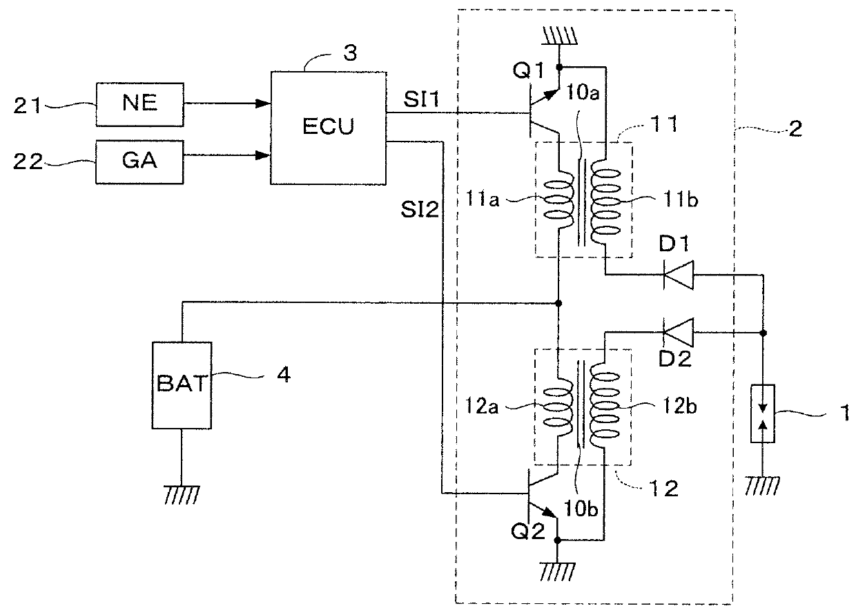
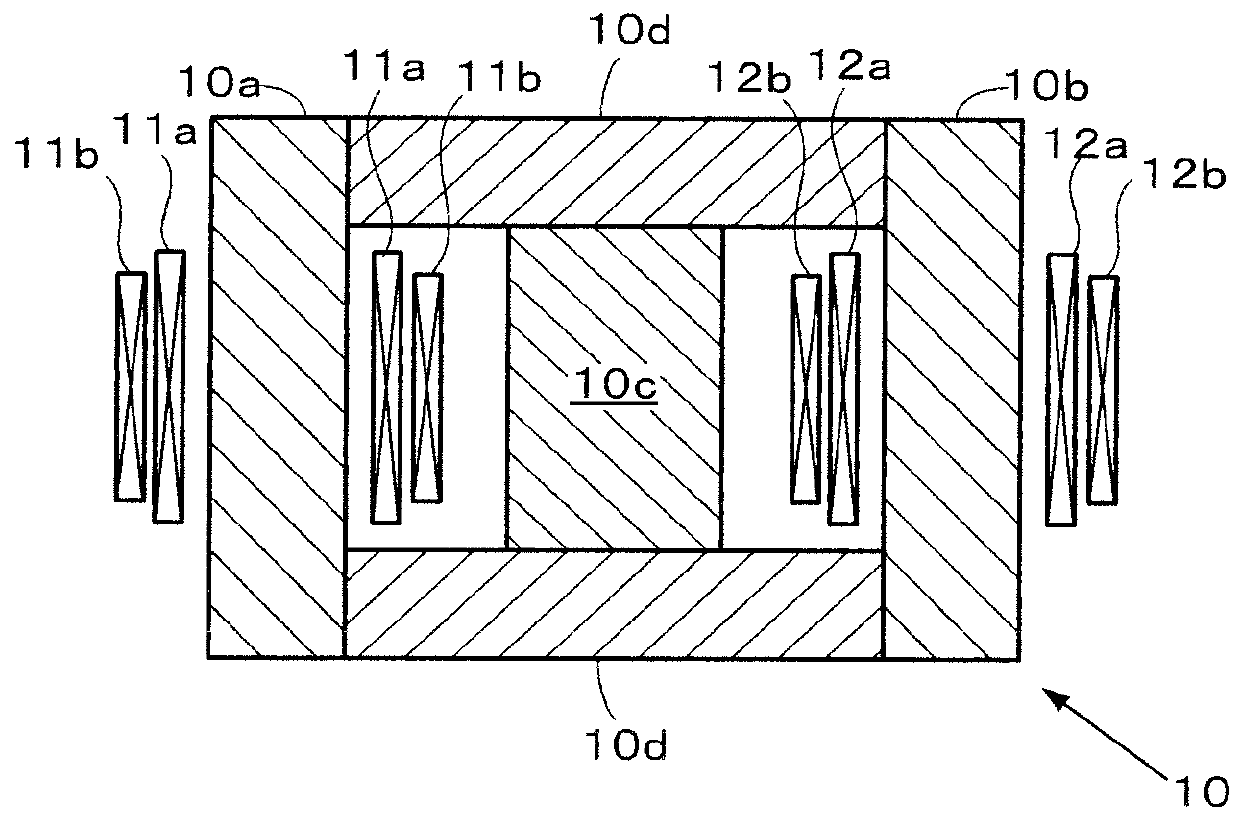
[0031]FIG. 1 shows a configuration of a main part of an ignition apparatus for an internal combustion engine according to one embodiment of the present invention, and FIG. 2 is a vertical section showing two coil pairs included in the ignition apparatus, and a core around which the coil pairs are wound.

[0032]The internal combustion engine (not shown) has, for example, four cylinders, and each cylinder is provided with an ignition plug 1. An actuating circuit 2 for generating a spark discharge in the ignition plug 1 is provided with two coil pairs 11 and 12. The first coil pair 11 is configured by winding a primary coil 11a and a secondary coil 11b around a core 10, and the second coil pair 12 is configured by winding a primary coil 12a and a secondary coil 12b around the core 10.

[0033]The core 10 is configured by assembling the components of laminated thin iron plates without an...


PUM


Abstract

An ignition apparatus for an internal combustion engine, comprising at least one ignition plug, an actuating circuit provided with first and second coil pairs corresponding to one ignition plug for generating spark discharge in the at least one ignition plug. First and second ignition signals respectively supplied to the first and second coil pair are generated so that a first discharge period and a second discharge period partially overlap with each other during an overlap discharge period, the overlap discharge period is made equal to a set overlap period, and a start timing of the first discharge period is prior to a start timing of the second discharge period. The first and second discharge periods are time periods of electric discharges generated by the first and second coil pairs. The set overlap period is set according to the first discharge period, a temporary cut threshold value, and a discharge start current value at the start timing of the first discharge period. The temporary cut threshold value is a minimum value of the discharge current value at which no temporary cut of the discharge current in the ignition plug occurs.

Description

BACKGROUND OF THE INVENTION[0001]1. Field of the Invention[0002]The present invention relates to an ignition apparatus for an internal combustion engine, and particularly to an ignition apparatus in which an actuating circuit for actuating one ignition plug is provided with two coil pairs, and multiple ignition is performed by generating a high secondary voltage at comparatively short time intervals.[0003]2. Description of the Related Art[0004]Japanese patent publication No. 5047247 (JP'247) discloses an ignition apparatus in which an actuating circuit for actuating one ignition plug is provided with two coil pairs, and ignition is performed by changing the used coil pair(s) according to electric discharge energy demand for the ignition plug. In this apparatus, ignition using one coil pair is performed when the electric discharge energy demand is comparatively low, and multiple ignition using two coil pairs in one cycle is performed in the boost-power ignition region where the elect...

Claims


Application Information

Patent Timeline
Patent Type & Authority Patents(United States)
IPC IPC(8): F02P15/10F02P15/08F02P5/15F02P11/00F02D41/18
CPCF02P15/08F02P5/1502F02P11/00F02P15/10F02D41/182F02D2200/101Y02T10/46Y02T10/40
Inventor KURAHASHI, MAKOTOKIMURA, NORITAKA
Owner HONDA MOTOR CO LTD
Why Eureka
Try Eureka