
Duct averaging sensor having a connector

a technology of duct averaging and connector, which is applied in the direction of instruments, heat measurement, heating types, etc., can solve the problems of poor control, air in the duct may be stratified, installation of the housing containing the sensor elements, and installation challenges for the installing technician, so as to facilitate the installation and replacement tasks.

Active Publication Date: 2016-05-31
TASSERON SENSORS
View PDF42 Cites 23 Cited by
  • Summary
  • Abstract
  • Description
  • Claims
  • Application Information

AI Technical Summary

Benefits of technology

The invention is a duct averaging sensor that has mating connectors and terminal connectors for joining sensor elements inside a duct to terminals on the outside wall of the duct. This design allows for separate installation and maintenance of the sensor, making it easier to replace or service. The connectors are securely connected, providing a reliable operation with a long service life. The sensor is water tight and seals the electrical connection between the sensor elements and terminals, protecting it from environmental factors. The sensor can be easily installed by drilling a hole in the duct wall and connecting the housing and terminal connectors, with no need for additional steps like installing a grommet or strain relief. Overall, the invention simplifies the installation process and reduces the risk of damage to the sensor.

Problems solved by technology

The weakness of a sensor utilizing a single sensor element is that the air in the duct may be stratified, with air at different locations in a cross section of the duct having different characteristics.
Since the single sensor element can detect the environmental condition at only a single location, the single sensor element will provide the control system with incomplete information, resulting in poor control.
In prior art duct averaging sensors, installation of the housing containing the sensor elements presents challenges to the installing technician, making proper installation a two-person job.
The step of passing the entire length of the housing through the drilled hole presents a hazard of flexing or kinking the housing.
Flexing or kinking the housing can damage the sensors, wires or connections contained within the housing.

Method used


Image

  • Duct averaging sensor having a connector
  • Duct averaging sensor having a connector
  • Duct averaging sensor having a connector

Examples


Embodiment Construction

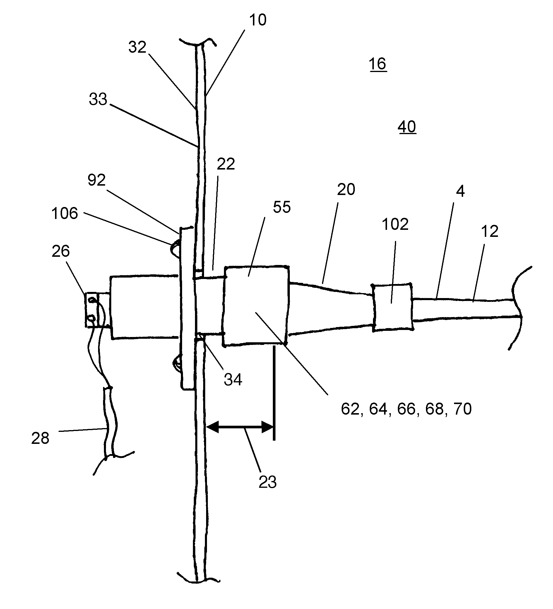
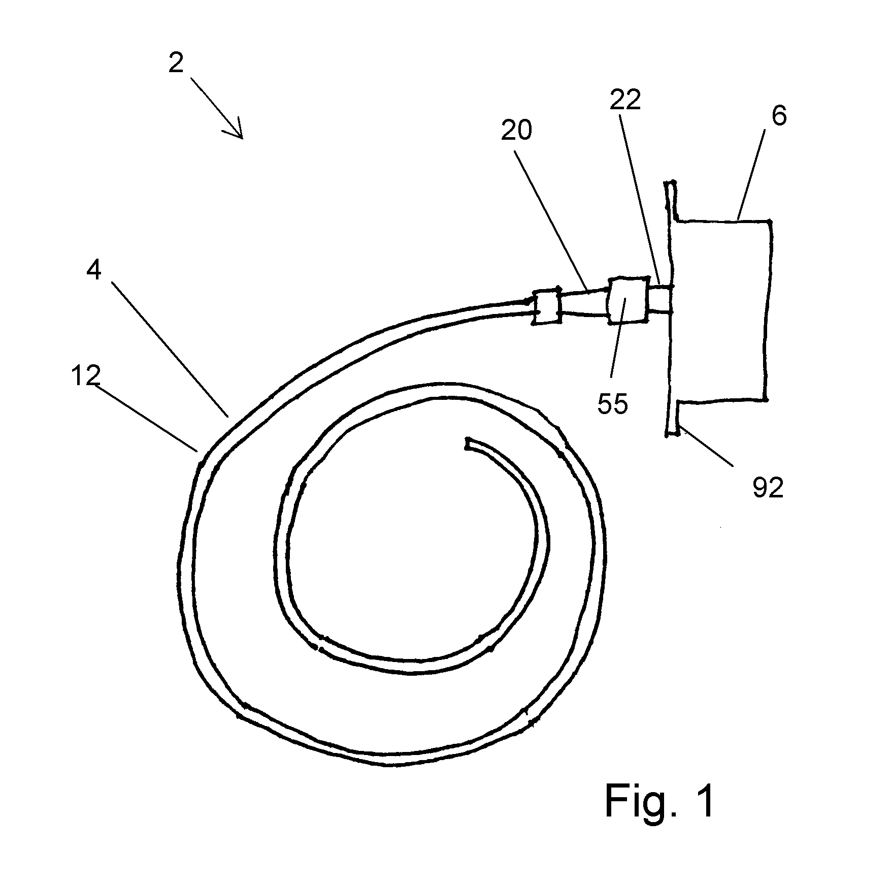
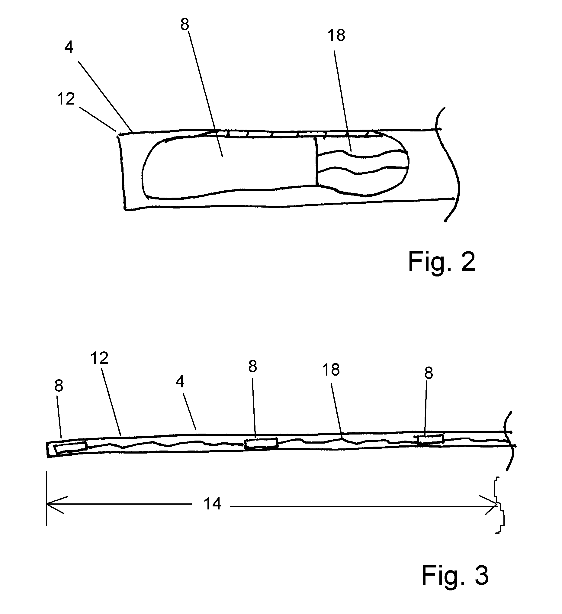
[0040]As shown by FIGS. 1, 2 and 3, the invention is a duct averaging sensor 2. The duct averaging sensor has a housing 4 and a terminal connector 22. In FIG. 1, the terminals 26 (shown by FIGS. 5 and 7) of the terminal connector 22 are enclosed within a junction box 6. The housing 4 contains a plurality of sensor elements 8. Each sensor element 8 is configured to detect an environmental condition within a duct 10. The housing 4 may be an elongated tube 12. Tube 12 may be composed of a bendable material, such as copper or aluminum. As received by a technician for installation, a housing 4 may be coiled, as shown by FIG. 1. Housing 4 is uncoiled and arranged within a duct 10 during the installation process, as described below.

[0041]As shown by FIG. 3, housing 4 has a length 14. The plurality of sensor elements 8 are distributed along the length 14 of the housing 4 and each sensor element 8 is configured to detect the environmental condition of the air (indicated by arrow 16 on FIG. 5...


PUM


Abstract

A duct averaging sensor has a plurality of sensor elements contained within a housing. A housing connector selectably joins the housing to a mating terminal connector. The terminal connector may be attached to the outside wall of a duct. The housing connector and terminal connector may be selectably attached and detached, with the housing extending into the inside of the duct. The selectable attachment of the housing to the terminal connector substantially eases installation and maintenance of the duct averaging sensor over prior art duct averaging sensors.

Description

I. RELATED APPLICATIONS[0001]This application is entitled to priority from Provisional Patent Application 61 / 589,063 filed Jan. 20, 2012 by the inventors herein. Provisional Patent Application 61 / 589,063 is hereby incorporated by reference as if set forth in full herein.II. BACKGROUND OF THE INVENTION[0002]A. Field of the Invention[0003]The present invention is directed to a duct averaging sensor for detecting an environmental condition of air within a duct. The duct averaging sensor is particularly suited to sensing the temperature of air as the air passes through the duct.[0004]B. Statement of the Related Art[0005]In a large heating, ventilation and air conditioning (HVAC) system, an air handling unit (AHU) may heat, cool, filter or humidify air to condition the air for the comfort of the occupants of a building. The AHU moves the conditioned air, known as supply air, through supply ducts and into the occupied spaces of the building. Return ducts transport return air from the occu...

Claims


Application Information

Patent Timeline
IPC IPC(8): G01D11/24G01N19/10H01R43/26G01K7/22B23P19/00G01K7/02
CPCG01N19/10B23P19/00G01D11/245G01K7/02G01K7/22H01R43/26H01R13/62H01R13/74G01K1/026G01K3/06G01K13/02G01K2201/00G01K13/024
Inventor VAN DIJK, THOMAS J.POOL, KEVIN ALAN
Owner TASSERON SENSORS
Learn More