Program for correcting charged particle radiation location, device for calculating degree of correction of charged particle radiation location, charged particle radiation system, and method for correcting charged particle radiation location

a technology for charging particles and radiation locations, applied in the field of correction, can solve the problems of reducing the positional accuracy of the drawing pattern formed on the workpiece, the superposition principle is not satisfied with respect to the spatial position function of the charged particle, and the accuracy of the calculation of the error amount cannot be obtained. , to achieve the effect of accurately correcting the irradiation position of the charged particle beam and increasing the positional accuracy of the drawing pattern

Active Publication Date: 2016-05-31
DAI NIPPON PRINTING CO LTD
View PDF6 Cites 4 Cited by
  • Summary
  • Abstract
  • Description
  • Claims
  • Application Information

AI Technical Summary

Benefits of technology

[0018]According to the invention, it is possible to correct accurately an irradiation position of a charged particle beam, such that a positional accuracy of a drawing pattern is increased.

Problems solved by technology

In a drawing process such as lithography using a charged particle beam, there have been some cases where a resist applied to a surface of a work piece is charged due to irradiation of the charged particle beam, and a trajectory of the charged particle beam is distorted due to charging, so that an error occurs in an irradiation position.
This has led to a decrease in a positional accuracy of a drawing pattern formed on the work piece.
However, according to electromagnetism, a superposition principle is satisfied with respect to an electric field or a potential, but the superposition principle is not satisfied with respect to a spatial position function for a charged particle.
Accordingly, there are some cases where an accurate result may not be obtained from a calculation of the error amount using the above-described convolution integration between the charge distribution and the response function.
However, in this case, as the charged particle beam approaches the charged position of a work piece, the strength of an electric field is close to infinity and it is impossible to perform a calculation due to excessive performance required of a computer, accordingly.
In this manner, there has been a problem in that it is impossible to calculate the error amount or the correction amount at the charged position.

Method used


Image

  • Program for correcting charged particle radiation location, device for calculating degree of correction of charged particle radiation location, charged particle radiation system, and method for correcting charged particle radiation location
  • Program for correcting charged particle radiation location, device for calculating degree of correction of charged particle radiation location, charged particle radiation system, and method for correcting charged particle radiation location
  • Program for correcting charged particle radiation location, device for calculating degree of correction of charged particle radiation location, charged particle radiation system, and method for correcting charged particle radiation location

Examples


first embodiment

[0027]Hereinafter, embodiments of the invention will be described with reference to the drawings.

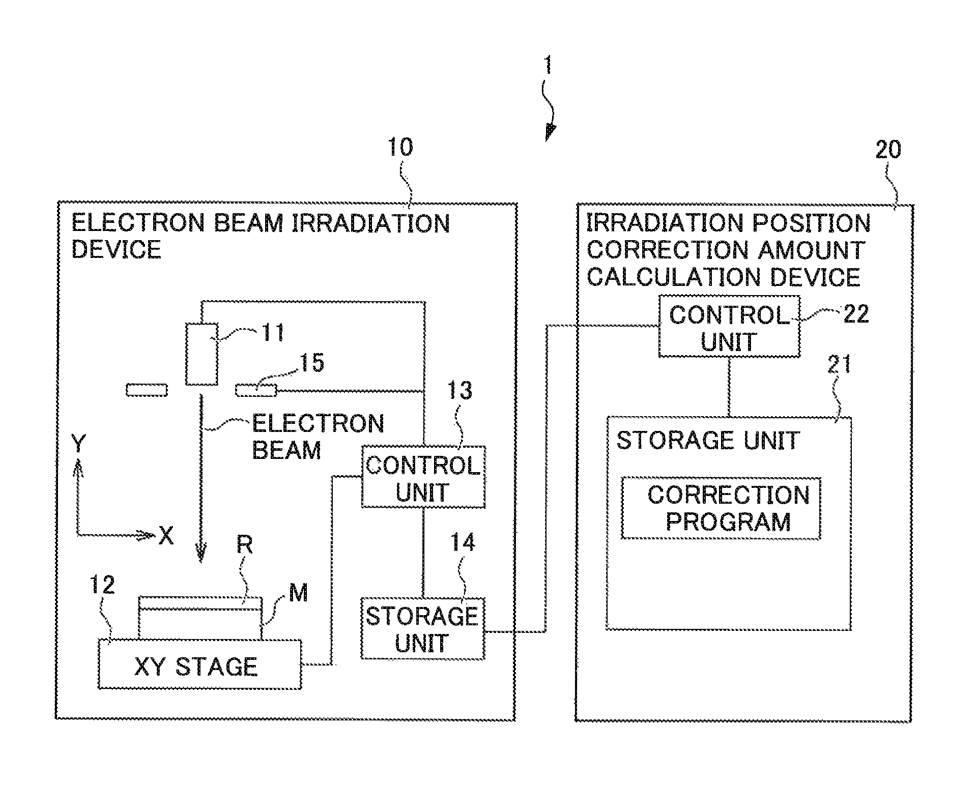
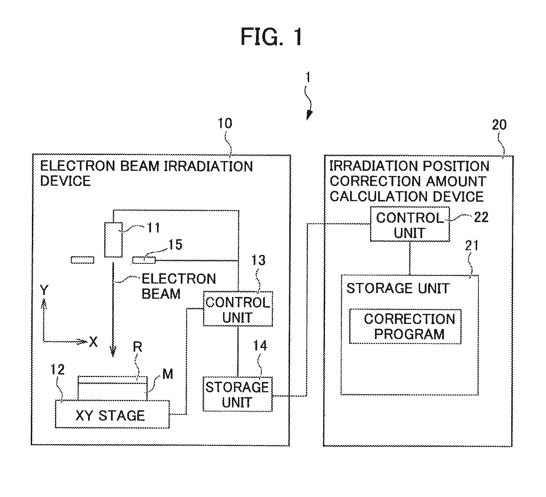
[0028]FIG. 1 is a diagram illustrating a configuration of a drawing system 1 according to an embodiment.

[0029]In FIG. 1, an electron beam irradiation direction is set to a Z-direction, and directions perpendicular to the irradiation direction are set to an X-direction and a Y-direction.

[0030]The drawing system (charged particle beam irradiation system) 1 is an apparatus for irradiating a mask substrate (work piece) 100 with an electron beam as a charged particle beam to draw a predetermined pattern on a mask substrate M to produce a photomask. As illustrated in FIG. 1, the drawing system 1 includes an electron beam irradiation device 10, a correction amount calculation device 20, and the like.

[0031]The electron beam irradiation device 10 includes an electron gun 11, an XY stage 12, a control unit 13, a storage unit 14, a deflector 15, and the like.

[0032]The electron gun 11 irradiates the...

modified example

[0104](1) In the embodiment, the example where the electron beam is used as a charged particle beam is described, but the invention is not limited thereto. For example, an ion beam or the like may be used as a charged particle beam.

[0105](2) In the embodiment, the example where the correction program is used for the case where the mask substrate M is irradiated with the electron beam is described, but the invention is not limited thereto. For example, the correction program may be used for the case where direct drawing is performed on a semiconductor wafer.

[0106](3) In the embodiment, the example where the drawing system 1 produces correction amount data in advance and, after that, irradiates the electron beam is described. However, the drawing system may produce the correction amount data while irradiating the electron beam.

[0107](4) In the embodiment, the example where the correction amount calculation device 20 provided to the drawing system 1 calculates the correction amount of ...


PUM


Abstract

The present invention provides a non-transitory medium storing a program for correcting an irradiation position of a charged particle beam, a correction amount calculation device, a charged particle beam irradiation system, and a method for correcting an irradiation position of a charged particle beam. The medium includes instructions for causing a control unit to perform actions including replacing charging of a resist with surface charges at an interface between the resist and a work piece, and calculating a charge density distribution of the surface charges; calculating a trajectory of a charged particle based on the charge density distribution; calculating an amount of error of the irradiation position of the charged particle beam based on the trajectory and calculating an amount of correction of the irradiation position of the charged particle beam based on the error amount.

Description

CROSS-REFERENCE TO RELATED APPLICATIONS[0001]This application is the national phase under 35 U.S.C. §371 of PCT International Application No. PCT / JP2014 / 051308, filed Jan. 22, 2014, which claims the benefit of Japanese Application No. 2013055276, filed Mar. 18, 2013, the entire contents of the aforementioned applications are hereby incorporated herein by reference.TECHNICAL FIELD[0002]The invention relates to a program for a correction program for a charged particle beam irradiation position, a correction amount calculation device for a charged particle beam irradiation position, a charged particle beam irradiation system, and a correction method for a charged particle beam irradiation position.BACKGROUND ART[0003]In a drawing process such as lithography using a charged particle beam, there have been some cases where a resist applied to a surface of a work piece is charged due to irradiation of the charged particle beam, and a trajectory of the charged particle beam is distorted due...

Claims


Application Information

Patent Timeline
Patent Type & Authority Patents(United States)
IPC IPC(8): H01J37/00H01J37/317H01J37/304H01J37/20
CPCH01J37/3045H01J37/20H01J37/3174H01J2237/30455H01J2237/004
Inventor OOKAWA, YOHEIOZAWA, HIDENORI
Owner DAI NIPPON PRINTING CO LTD
Why Eureka
Try Eureka