Laser alignment device with a movable mirror, laser-target alignment sensor with movable mirrors and laser alignment method

a laser-target alignment and mirror technology, which is applied in the direction of instruments, optical elements, television systems, etc., can solve the problems of interference, laser-target alignment sensors cannot obtain accurate feedback of each incident laser beam, and overlap of feedback spots, etc., to achieve fast and accurate laser alignment, reduce alignment time, and improve accuracy

Inactive Publication Date: 2016-06-07
INST OF AUTOMATION CHINESE ACAD OF SCI
View PDF5 Cites 2 Cited by
  • Summary
  • Abstract
  • Description
  • Claims
  • Application Information

AI Technical Summary

Benefits of technology

[0007]The present disclosure provides a laser alignment device with a movable mirror, a laser-target alignment sensor with movable mirrors comprising the laser alignment device. The laser alignment device is provided with movable mirrors system to achieve linear motion of the movable mirror with high accuracy in a small range, which in turn achieves fast and accurate alignment of the laser. It solves the problem of laser spots overlapping, reduces alignment time and improves shooting accuracy.
[0022]As mentioned above, the laser alignment device with a movable mirror according to the present disclosure and the laser-target alignment sensor with movable mirrors including the same utilize movable mirrors system to solve the problem of overlapping a plurality of feedback images of the target, to reduce alignment time and to improve shooting accuracy. Thus, it improves an efficiency of a laser-target alignment process.
[0023]The present disclosure achieves accurate alignment of a plurality of beams of laser on a target, for example, in the inertia confinement fusion, to solve the problem of laser spots overlapping, to reduce alignment time and to improve shooting accuracy.
[0024]Furthermore, the present disclosure is directed to a rapid laser-target alignment process for the movable mirror on the basis of the structure of the above movable mirror system, which can rapidly and simultaneously align a plurality of beams of laser, save an adjustment time, and improve a shooting efficiency.

Problems solved by technology

However, when several hundred of laser beams are guided simultaneously to shoot the target, the laser-target alignment sensor has the problem that feedback spots are overlapped with each other and interferences with each other.
Consequently, the laser-target alignment sensor cannot obtain accurate feedback of each incident laser beam.
The problem may be solved by guiding a single laser beam each time to shoot the target, which, however, is very time-consuming.
The more time for adjustment, the more serious an effect of the system drift on the accuracy is.
Consequently, the compromise in the laser-target alignment is almost impossible.
That is, the conventional laser-target alignment sensor cannot achieve the compromise between accuracy and efficiency of adjustment in the laser-target alignment process.
Moreover, the conventional laser-target alignment sensor can only provide information about a position of a laser spot on a screen, but not information about a spatial location of the laser beam, such as a pitch angle of the incident laser beam.
The conventional laser-target alignment sensor cannot be used to control spatial distribution of laser beams in a target chamber to optimize energy distribution of the laser beams in the target chamber.

Method used


Image

  • Laser alignment device with a movable mirror, laser-target alignment sensor with movable mirrors and laser alignment method
  • Laser alignment device with a movable mirror, laser-target alignment sensor with movable mirrors and laser alignment method
  • Laser alignment device with a movable mirror, laser-target alignment sensor with movable mirrors and laser alignment method

Examples


first embodiment

[0049]The structure of a laser alignment device with a movable mirror according to the present disclosure and its principle will be described below.

[0050]FIG. 2 schematically illustrates a structure of a laser alignment device with a movable mirror according to the first embodiment according to the present disclosure.

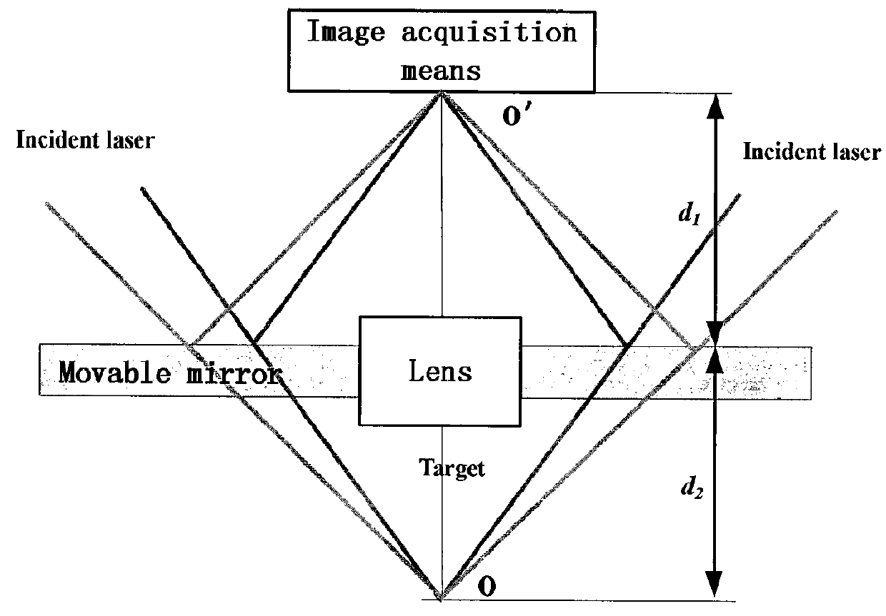
[0051]As shown in FIG. 2, the laser alignment device with a movable mirror comprises a target (O), a plurality of beams of laser emitted from a plurality of laser sources and illuminating the target, an image acquisition means for acquiring incident lights to form an image, a lens which is located between the target and the image acquisition means and is used to form an image of the target in the image acquisition means. It further includes movable mirrors between the target and the image acquisition means, for reflecting the plurality of beams of laser emitted from a plurality of laser sources onto the image acquisition means to form laser spots. The movable mirror can...

second embodiment

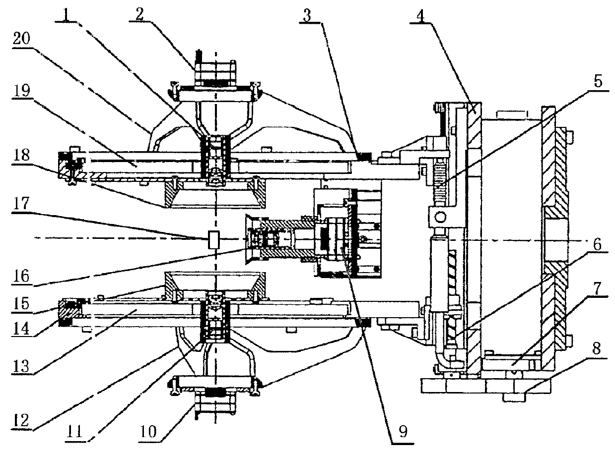
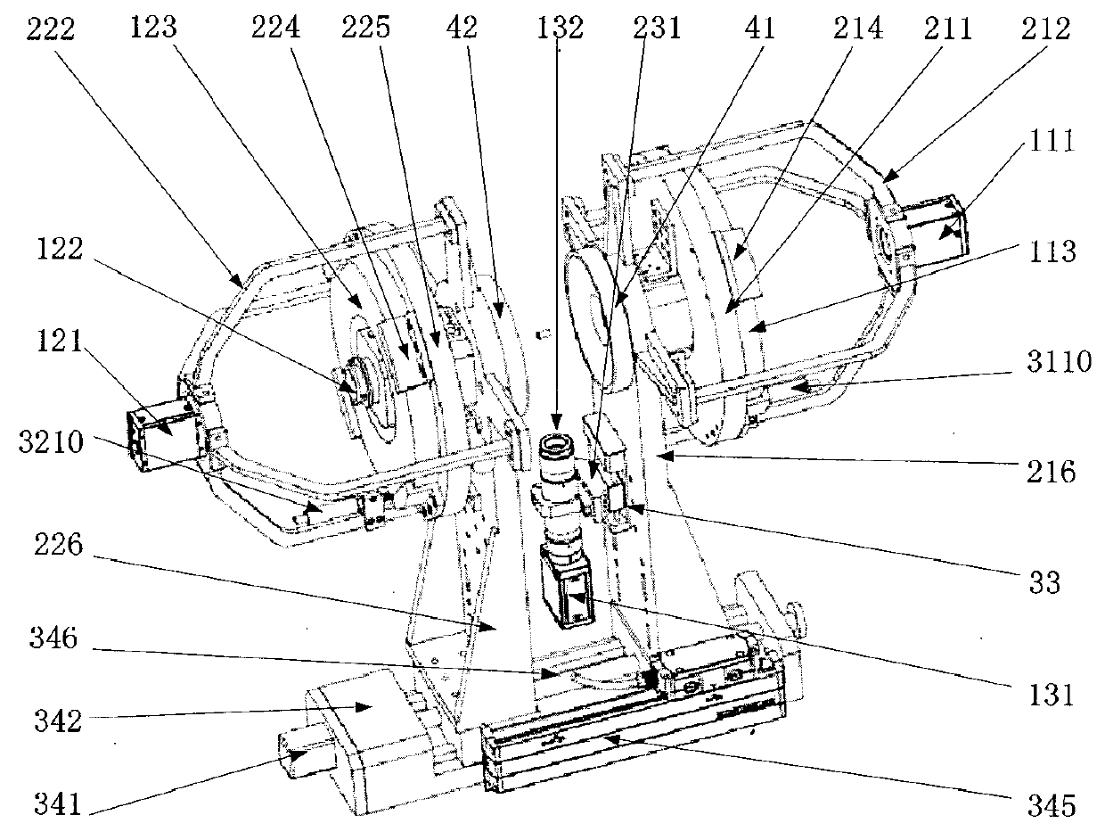
[0057]The structure of a laser-target alignment sensor with movable mirrors according to the present disclosure will be described below. FIG. 3 schematically illustrates a three dimensional structure of a laser-target alignment sensor with movable mirrors according to the present disclosure. FIG. 4 is a front view showing a structure of a laser-target alignment sensor with movable mirrors according to the present disclosure. FIG. 5 is a left view showing a structure of a laser-target alignment sensor with movable mirrors according to the present disclosure.

[0058]As shown in FIGS. 3 to 5, the laser-target alignment sensor with the movable mirror according to the present disclosure comprises a first laser alignment device (on the left side in the figure), a second laser alignment device (on the right side in the figure), a middle visual inspection means, a differential focusing system, a servo driving system for the movable mirrors. The first laser alignment device and the second lase...

third embodiment

[0089]The principle of a laser alignment device with a movable mirror according to the present disclosure will be described below.

[0090]

[0091]FIG. 8 illustrates an example of the relation between the motion of mirror and the trajectory of the laser spots.

[0092]As shown in FIG. 8, a laser beam is incident at the first point {circle around (1)}, reflected by the mirror, and reaches the CCD. The image at the CCD is shown in a plane view of the CCD. When the mirror moves towards the CCD in a vertical direction, an image point at the CCD will move in an arrow direction. Specifically, in accordance with an embodiment, when the mirror is located at the conjugate position, the laser beam is reflected at the second point {circle around (2)} at the mirror, and has a laser spot at the second point {circle around (2)} in an image plane of the CCD. When the mirror moves towards the CCD to the position I, the laser beam is reflected at the third point {circle around (3)} at the mirror, and has a ...


PUM


Abstract

A laser alignment device with at least one movable mirror, a laser-target alignment sensor with movable mirrors and a laser alignment method are disclosed. The laser alignment device with the movable mirror comprises an image acquisition means for collecting incident lasers, a moveable mirror for reflecting the lasers to the image acquisition means and is operable to move linearly with respect to the image acquisition means, and a lens for forming an image of a target in the image acquisition means. The present disclosure achieves linear motion of the movable mirror with high accuracy in a small range, which in turn achieves fast and accurate alignment of the laser. It solves the problem of laser spots overlapping, reduces alignment time and improves shooting accuracy.

Description

CROSS-REFERENCE TO RELATED APPLICATION[0001]This application claims the benefit of PCT Patent Application No. PCT / CN2011 / 073473, filed Apr. 28, 2011, in the State Intellectual Property Office of China, which is incorporated herein by reference in its entirety.TECHNICAL FIELD[0002]The disclosure relates to an alignment device for aligning a plurality of beams of laser, and in particular to a laser alignment device with a movable mirror, a laser-target alignment sensor with movable mirrors and a laser alignment method using the same.BACKGROUND[0003]The technique about accurate alignment of a plurality of beams of laser can be applied to the industrial field of sophisticated manufacture detection, and is also applicable to other specific fields in which a plurality of beams of laser are applied to be aligned to a tiny object. In these applications, a dedicated laser alignment device is used to guide several hundred of beams of laser to a target region within a range of several millimet...

Claims


Application Information

Patent Timeline
Patent Type & Authority Patents(United States)
IPC IPC(8): G01B11/14H04N7/18G02B7/00G02B26/08
CPCG02B7/005G02B26/0816
Inventor WU, BAOLINZHANG, WENSHENGSHI, YALIHAO, YINXINGLI, HAIPENGDONG, QIULEIWANG, HAOXINGZHANG, ZHENGTAO
Owner INST OF AUTOMATION CHINESE ACAD OF SCI
Why Eureka
Try Eureka