Chordwise lay-up of fibre sheet material for turbine blades

a technology of fibre sheet material and turbine blades, which is applied in the direction of machines/engines, other domestic articles, and final product manufacture. it can solve the problems of increasing the lay-up speed, increasing the amount of material waste, so as to reduce the amount of waste sheet materials, and avoid or minimize the above-mentioned amount of material waste.

Active Publication Date: 2016-06-28
VESTAS WIND SYST AS
View PDF8 Cites 1 Cited by
  • Summary
  • Abstract
  • Description
  • Claims
  • Application Information

AI Technical Summary

Benefits of technology

[0007]A first object of the invention is to avoid or minimize the aforementioned amount of material waste. By laying the material laterally in the mould instead of lengthwise the amount of waste is minimized. This is because when laying the sheet material in the mould, from the part which shapes the leading edge of the blade toward the part forming the trailing edge of the blade, and laying a next sheet of material overlapping the formerly laid sheet, from the part of the mould, which shapes the trailing edge of the blade, and towards the part of the mould shaping the leading edge of the blade, then the cutting angle of the formerly laid sheet nearly, but not completely, equals the required angle for the next laid sheet in order to conform to the mould. Hence, only a minimal amount of trimming of the next layer is required, whereby the amount of waste sheet material is greatly reduced. And of course, the same effect is present when laying an additional sheet from the part of the mould shaping the leading edge of the blade towards the part of the mould shaping the trailing edge of the blade.

Problems solved by technology

However, due to the shape of the blade, which is very broad in the area around where maximum chord is located and very pointy at the tip of the blade, there is a massive amount of material waste when the sheets of uniform width are cut to conform to such a shape.
Often the precise cutting of the sheet material to be located in a certain position is done prior to the actual use of the sheet material, which increases lay-up speed, but at the same time increases material waste.
Retrieving the cut away material by splicing it to form a usable material has not been found feasible, as joints, like cut and overlay ends, have not shown proper strength performance.

Method used


Image

  • Chordwise lay-up of fibre sheet material for turbine blades
  • Chordwise lay-up of fibre sheet material for turbine blades
  • Chordwise lay-up of fibre sheet material for turbine blades

Examples


Embodiment Construction

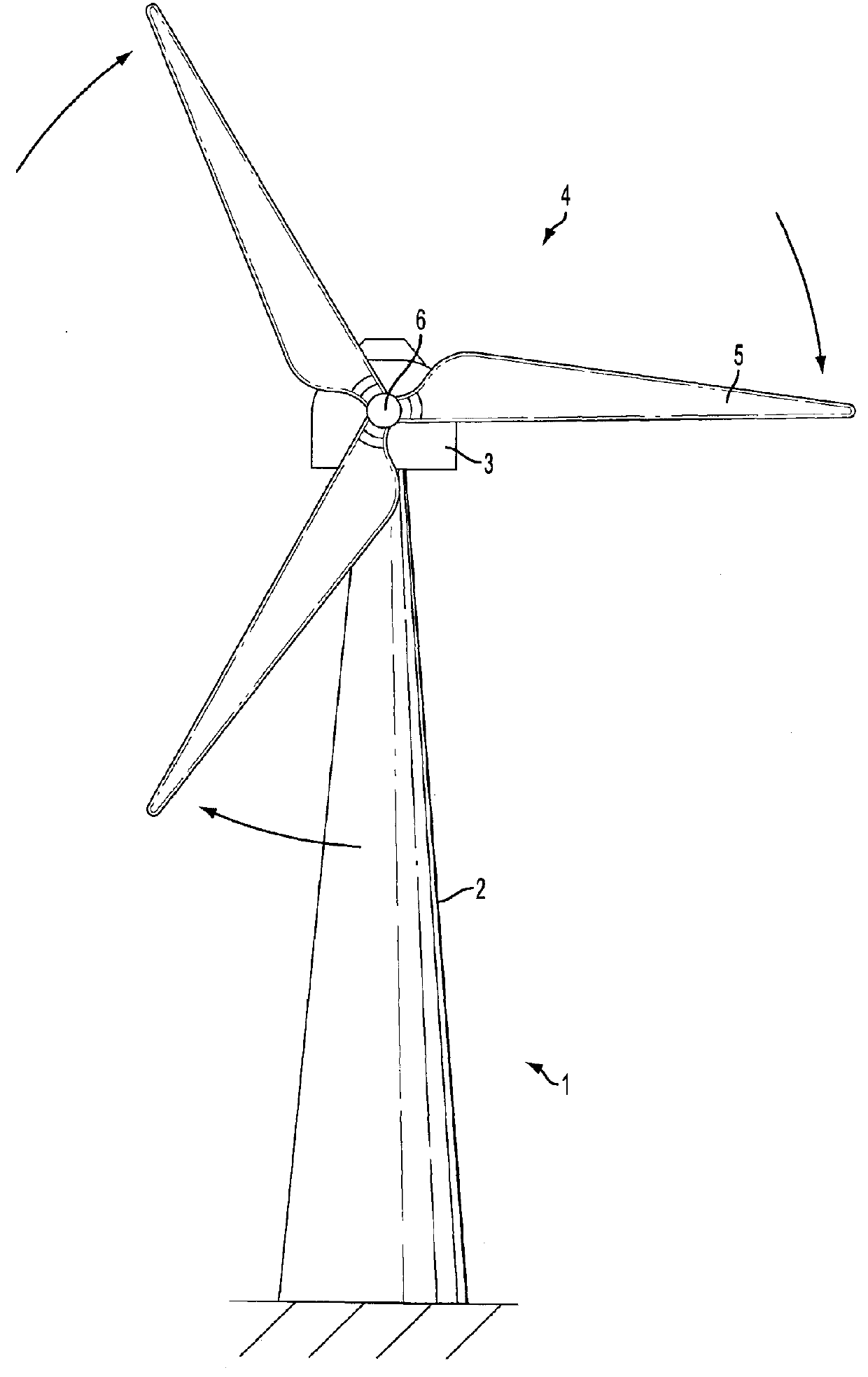
[0040]With reference to FIG. 1, the present invention relates to materials, manufacture etc. of a blade for a wind turbine 1.

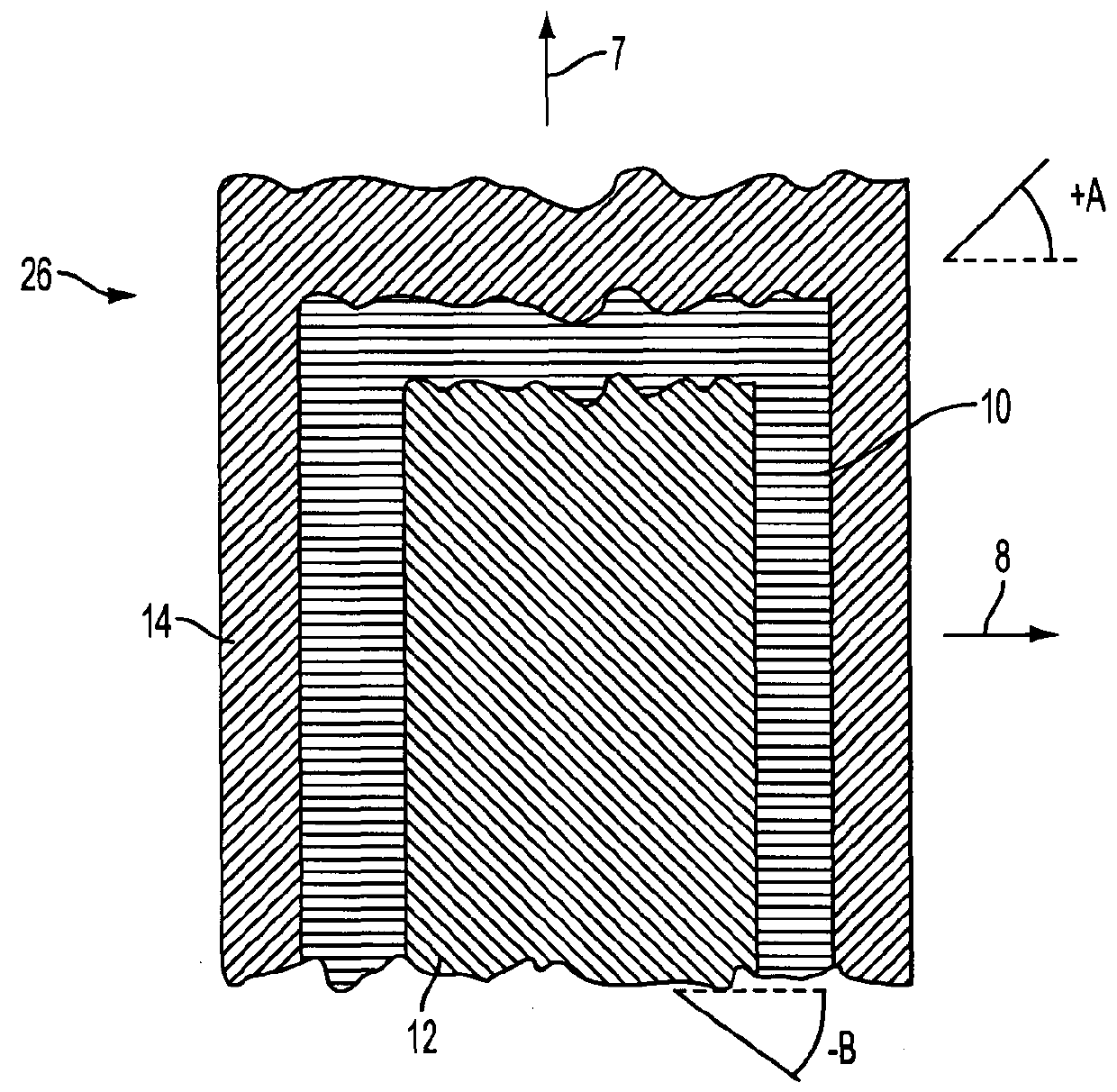
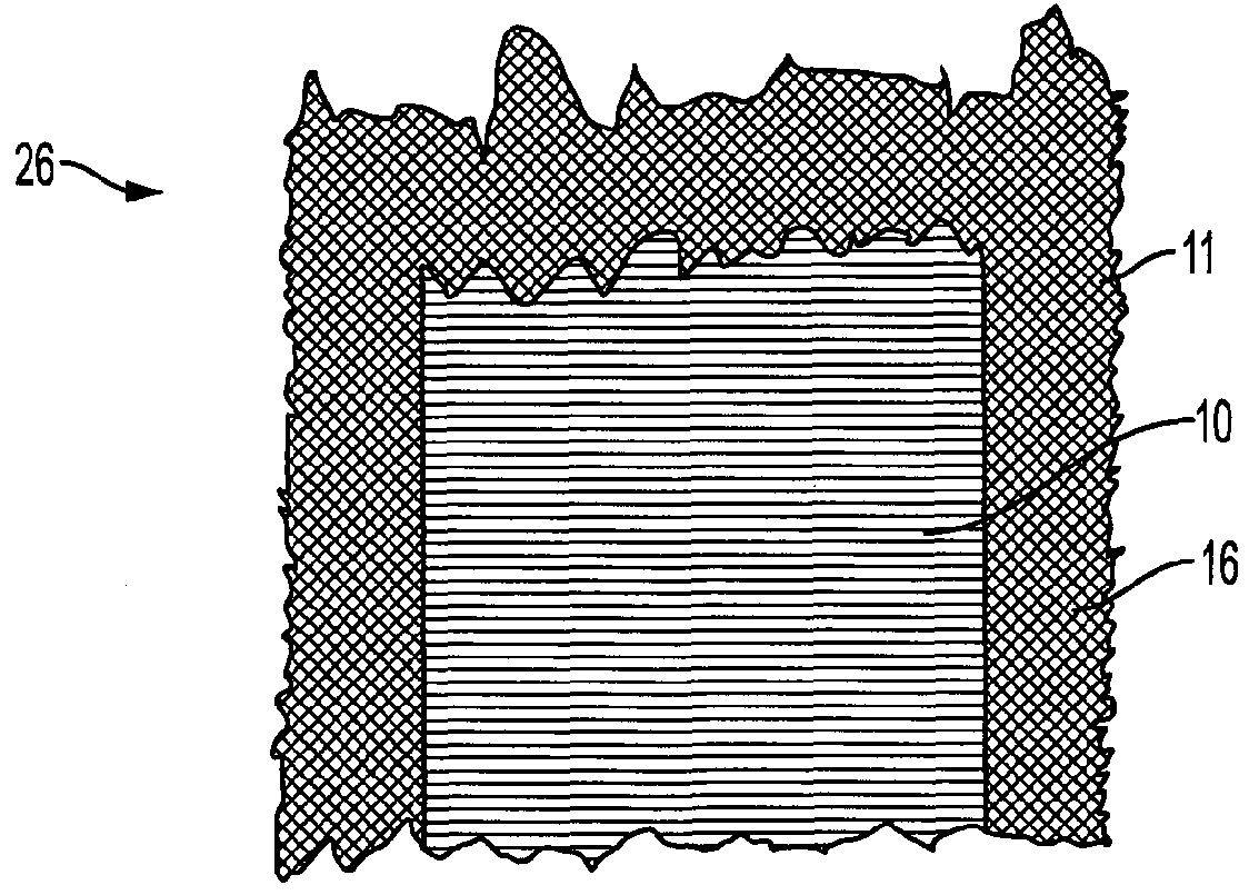
[0041]FIG. 2 shows an oblong fibre sheet material 26 for wind turbine blades, the fibre sheet material having a lengthwise direction 7 and a lateral direction 8. The sheet 26 comprises three stacked fibre layers 10, 12, 14, where the layer 14 is a surface layer and a lateral fibre layer 10 is a unidirectional layer, which has mainly fibres in the lateral direction 8. Each layer 10, 12, 14 has lengthwise side faces going in the lengthwise direction 7. The surface layer 14 is having a width, which in the lateral direction is broader than the lateral, unidirectional layer 10. The unidirectional layer 10 is positioned relative to the surface layer 14 such that the surface layer 14 overlaps the unidirectional layer 10 at both lengthwise side faces of the unidirectional layer. The lateral, unidirectional fibre layer 10 is placed on top of the surface layer 14, which...


PUM

PropertyMeasurementUnit
diameteraaaaaaaaaa
anglesaaaaaaaaaa
thicknessaaaaaaaaaa

Abstract

The present invention relates to a fibre sheet material and method of laying up fibre sheet material to manufacture wind turbine blades. The invention further comprises a blade manufactured by the method as well a use of such a blade. One aspect relates to an oblong fibre sheet material (26) for wind turbine blades, where a surface layer (14) is having a width, which in the lateral direction is broader than a lateral, unidirectional layer (10), and lengthwise side faces of at least the surface layer is provided with a thinning of a thickness of the layer to obtain favourable joints. Another aspect concerns manufacturing a wind turbine blade shell comprising laying fibre sheet (26) materials in a blade mould (20), where the sheet materials lengthwise are positioned in a direction corresponding to a chordwise direction of a turbine blade direction of the mould and overlapping in a spanwise direction. The effect obtained is a significant reduction in the amount of waste material compared to laying fibre sheets in the spanwise direction.

Description

TECHNICAL FIELD[0001]The present invention relates to a fibre sheet material and method of laying up fibre sheet material to manufacture fibre reinforced composite products, such as in this case, in particular wind turbine blades. The invention further comprises a blade manufactured by the method as well as a use of such a blade.BACKGROUND OF THE INVENTION[0002]FIG. 1 illustrates a wind turbine 1. The wind turbine comprises a wind turbine tower 2 on which a wind turbine nacelle 3 is mounted. A wind turbine rotor 4 comprising at least one wind turbine blade 5 is mounted on a hub 6. The hub 6 is connected to nacelle 3 through a low speed shaft (not shown) extending from the nacelle front. The wind turbine illustrated in FIG. 1 may be a small model intended for domestic or light utility usage, or may be a large model, such as those that are used in large scale electricity generation or on a wind farm for example. In the latter case, the diameter of the rotor could be as large as 100 me...

Claims


Application Information

Patent Timeline
Patent Type & Authority Patents(United States)
IPC IPC(8): F01D5/28B29C70/30B29C70/20B29C70/54F03D1/06B32B5/26B32B3/26B32B3/02B32B5/02B23P15/04B29L31/08
CPCF01D5/282B23P15/04B29C70/202B29C70/30B29C70/545B32B3/02B32B3/263B32B5/024B32B5/26F03D1/0675B29L2031/085F05B2230/50F05B2250/313F05B2280/6003Y02E10/721Y02P70/523Y10T29/49337Y10T428/2476Y10T428/24124Y02E10/72Y02P70/50B29C70/302
Inventor BECH, ANTON
Owner VESTAS WIND SYST AS
Why Eureka
Try Eureka