Systems and methods for refueling canister system

a canister system and canister technology, applied in the direction of machines/engines, mechanical equipment, transportation and packaging, etc., can solve the problem of limited amount of bleeding, and achieve the effect of reducing the release of fuel vapors

Active Publication Date: 2016-07-12
FORD GLOBAL TECH LLC
View PDF16 Cites 4 Cited by
  • Summary
  • Abstract
  • Description
  • Claims
  • Application Information

AI Technical Summary

Benefits of technology

[0002]Vehicle fuel systems include evaporative emission control systems designed to reduce the release of fuel vapors to the atmosphere. For example, vaporized hydrocarbons (HCs) from a fuel tank may be stored in a fuel vapor canister packed with an adsorbent which adsorbs and stores the vapors. At a later time, when the engine is in operation, the evaporative emission control system allows the vapors to be purged into the engine intake manifold for use as fuel.
[0004]When a vehicle operator refuels the vehicle, the fuel cap may be locked until venting is allowed to sufficiently reduce tank pressure. The inventors herein have developed systems and methods to handle depressurization during refueling events. In one example, a method comprises: before refueling a fuel tank having a pressure above a first predetermined pressure, releasing the pressure through a first valve to the predetermined pressure and then closing the first valve and opening a second valve to further reduce the pressure to a second predetermined pressure; and if flow through the second valve is less than desired, then opening the first valve until the second predetermined pressure is reached. Preferably the fuel cap is unlocked when the second predetermined pressure, typically around atmospheric pressure, is reached. In this way, depressurization is always achieved in a timely manner.
[0005]In another example, the method comprises: before refueling a fuel tank having a pressure above a first predetermined pressure, and when flow through a first and a second valve coupled to the fuel tank is at least at a desired flow, releasing the pressure through a first valve to the first predetermined pressure and then closing the first valve and opening a second valve to further reduce the pressure to a second predetermined pressure; and if flow through the first valve is less than desired, then opening the second valve until the first predetermined pressure is reached. Further, the second valve may be pulsed to gradually release pressure. In this way, the second valve may be advantageously used to release fuel tank pressure if flow through the first valve is less than desired.
[0006]In still another example, the method comprises: before refueling a fuel tank having a pressure below a first predetermined pressure, releasing the pressure through a second valve to a second predetermined pressure; and if the second valve is restricted and the pressure does not reach the second predetermined pressure within an expected time, then opening a first valve until the second predetermined pressure is reached, the first valve normally being used when the pressure is above the first predetermined pressure to reduce the pressure to the first predetermined pressure. In this way, prior to a refueling event, the fuel tank may be depressurized even if one of the two valves is diagnosed as having less than desired flow.

Problems solved by technology

When the engine is not running, some pressure may be bled through the canister to atmosphere, but the amount of this bleeding is limited to prevent escape of fuel vapors from the tank or canister into the atmosphere.

Method used


Image

  • Systems and methods for refueling canister system
  • Systems and methods for refueling canister system
  • Systems and methods for refueling canister system

Examples


Embodiment Construction

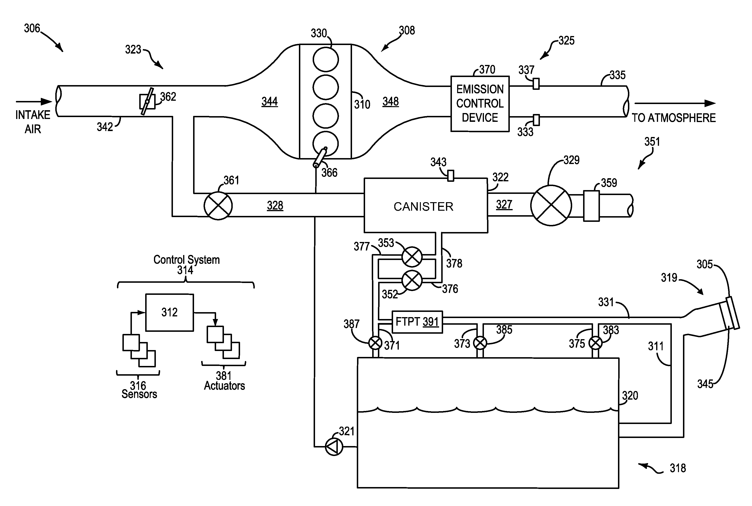
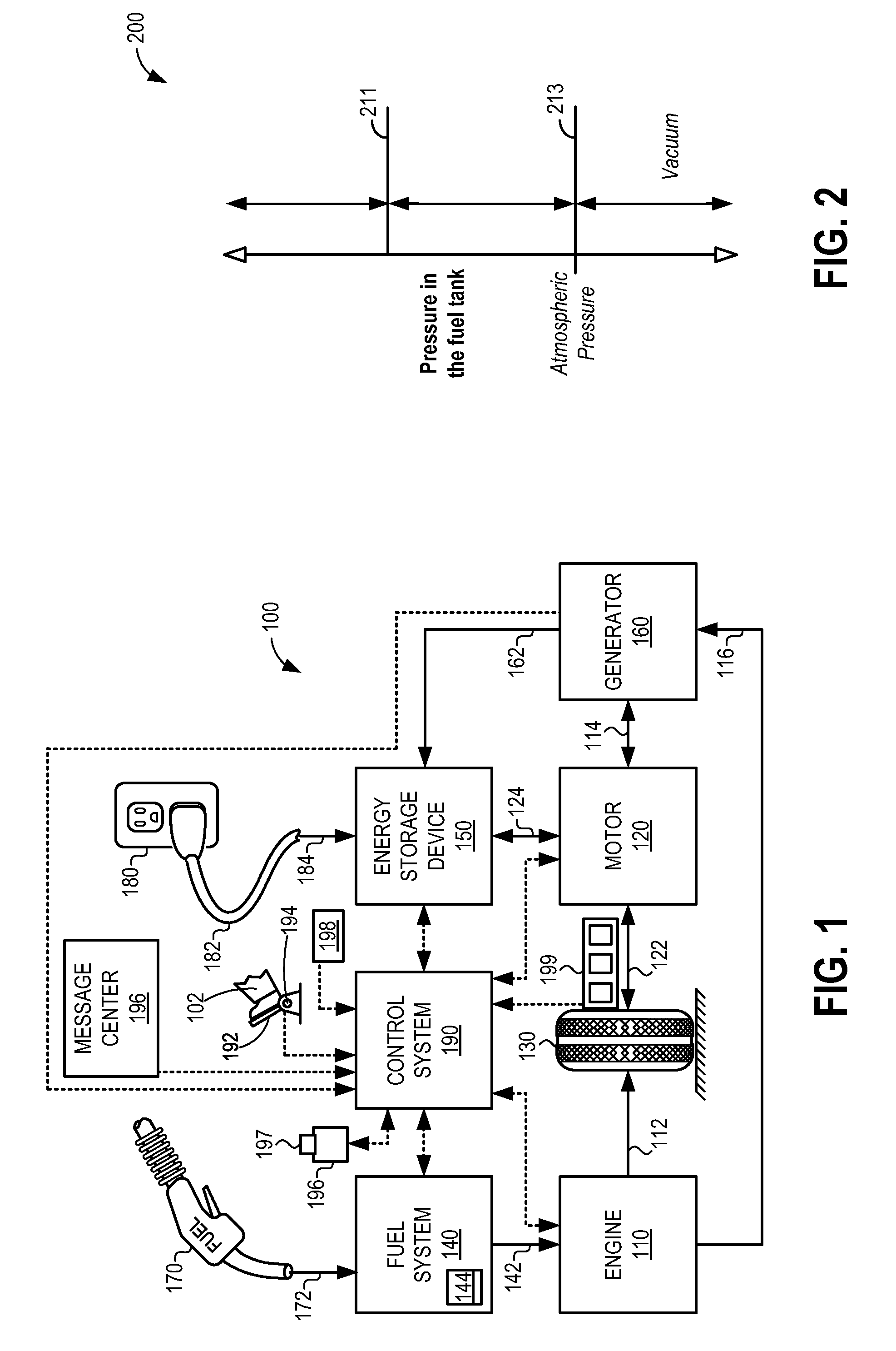
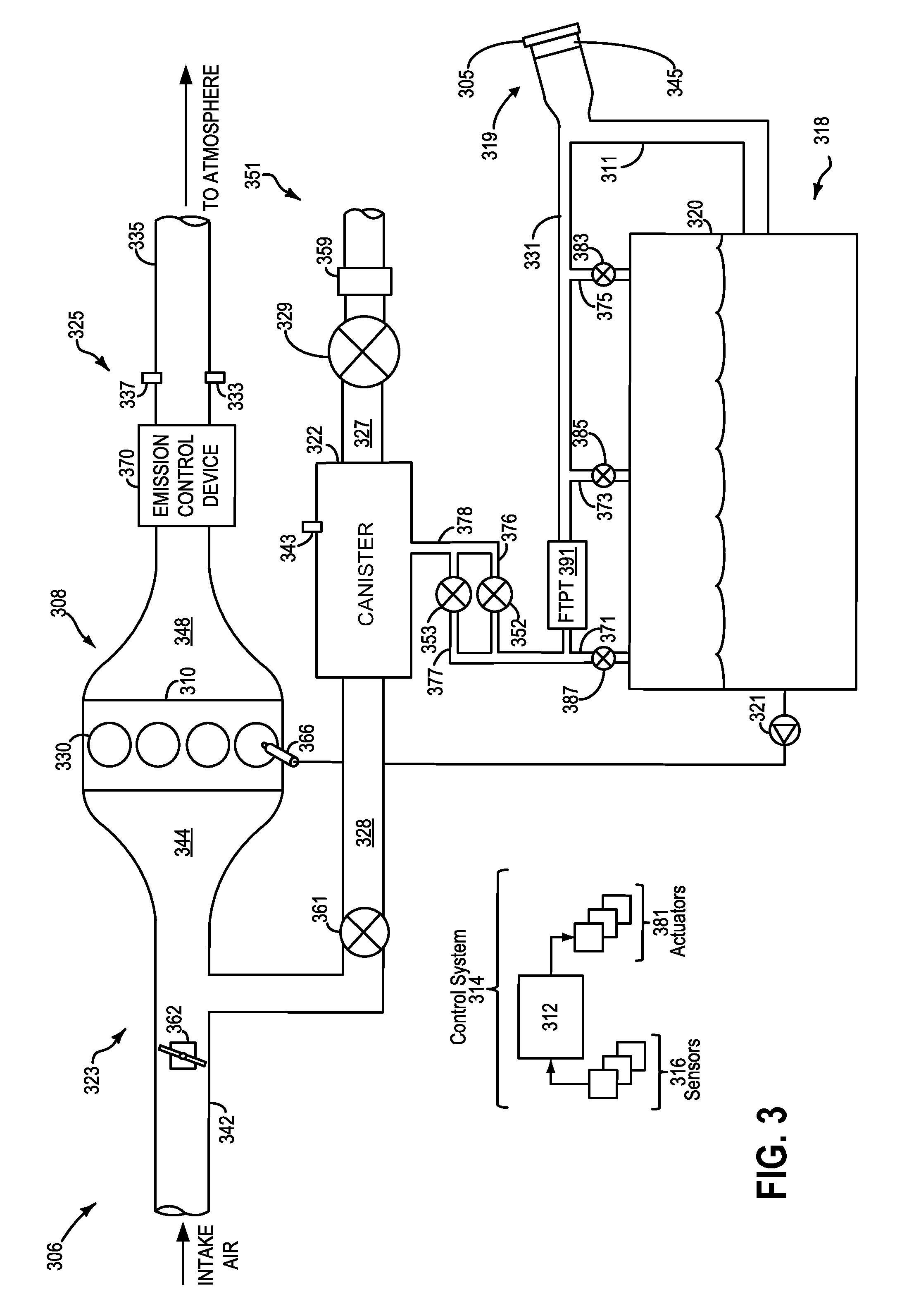
[0019]The following description relates to systems and methods for depressurizing a fuel tank from either positive or negative pressures prior to a refueling event. The fuel tank may be included in a vehicle, such as a hybrid electric vehicle, as shown in FIG. 1. The vehicle may include a fuel system and an evaporative emissions system, as shown in FIG. 3. The fuel system may be coupled to the evaporative emissions system via a tank pressure valve and a refueling valve, the two valves in parallel, as shown by FIG. 3. Pressure within the fuel tank may be higher than a first predetermined threshold, between a first predetermined threshold and a second predetermined threshold (or atmospheric pressure), or lower than a second predetermined threshold (or atmospheric pressure) as shown in FIG. 2. A refueling request may be followed by various depressurization routines (FIG. 4) based on the existing pressure within the tank. The depressurization routines of FIGS. 5, 6, and 7 utilize one or...


PUM


Abstract

Methods and systems are described for depressurizing a fuel tank prior to refueling. In one example, before refueling the fuel tank having a pressure above a first predetermined pressure, the pressure may be released through a first valve to the first predetermined pressure and the first valve may be closed. Further, a second valve may be opened to further reduce the pressure to a second predetermined pressure, and if flow through the second valve is less than desired, then the first valve may be opened until the second predetermined pressure is reached.

Description

TECHNICAL FIELD[0001]The field of the invention is related to fuel tank refilling of motor vehicles, and hybrid vehicles in particular.BACKGROUND AND SUMMARY[0002]Vehicle fuel systems include evaporative emission control systems designed to reduce the release of fuel vapors to the atmosphere. For example, vaporized hydrocarbons (HCs) from a fuel tank may be stored in a fuel vapor canister packed with an adsorbent which adsorbs and stores the vapors. At a later time, when the engine is in operation, the evaporative emission control system allows the vapors to be purged into the engine intake manifold for use as fuel.[0003]When the engine is not running, some pressure may be bled through the canister to atmosphere, but the amount of this bleeding is limited to prevent escape of fuel vapors from the tank or canister into the atmosphere. Accordingly, pressure may build in the fuel tank. This is particularly the case with hybrid vehicles where the internal combustion engine is not always...

Claims


Application Information

Patent Timeline
Patent Type & Authority Patents(United States)
IPC IPC(8): F02M25/08B60K6/20
CPCF02M25/0836B60K6/20Y10S903/902
Inventor BOLGER, BRYAN MICHAELLINDLBAUER, MICHAEL PAULPETERS, MARK W.
Owner FORD GLOBAL TECH LLC
Why Eureka
Try Eureka