
Apparatus for conveying and plant for surface-treating articles

a technology for conveying equipment and surface-treating articles, which is applied in the direction of mechanical conveyors, conveyor parts, packaging, etc., can solve the problems of increasing the total operating cost of the plant, adversely affecting the energy balance of the vehicle body to be treated, and consuming a large amount of energy for heating and cooling the respective skid

Active Publication Date: 2016-07-19
EISENMANN AG
View PDF14 Cites 8 Cited by
  • Summary
  • Abstract
  • Description
  • Claims
  • Application Information

AI Technical Summary

Benefits of technology

The invention is a conveyor system for vehicles that can carry skids and other objects. The system includes a continuous drive train with coupling members that can cooperate with standardized holding components of vehicle bodies. The coupling members can be pivoted and transferred between an operating position and a return position. The overall height of the conveyor device is low, and the system can be used with different treatment zones and conveying systems. The technical effects of the invention include increased flexibility in conveyable vehicle bodies and reliable conveyance of vehicle bodies and objects.

Problems solved by technology

As a result, in each drying procedure, a considerable amount of energy is used for heating and cooling the respective skid.
All in all, in the case of commercially known conveying devices of the type mentioned at the outset which cooperate with skids, the total energy balance in terms of the vehicle bodies to be treated is adversely affected and the total operating costs of the plant are therefore increased.

Method used


Image

  • Apparatus for conveying and plant for surface-treating articles
  • Apparatus for conveying and plant for surface-treating articles
  • Apparatus for conveying and plant for surface-treating articles

Examples


Embodiment Construction

[0053]While this invention is susceptible of embodiment in many different forms, there is shown in the drawings and will herein be described in detail one or more embodiments with the understanding that the present disclosure is to be considered as an exemplification of the principles of the invention and is not intended to limit the invention to the embodiments illustrated.

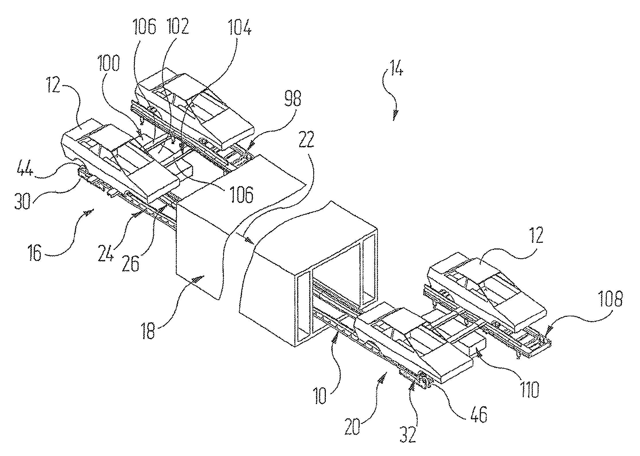
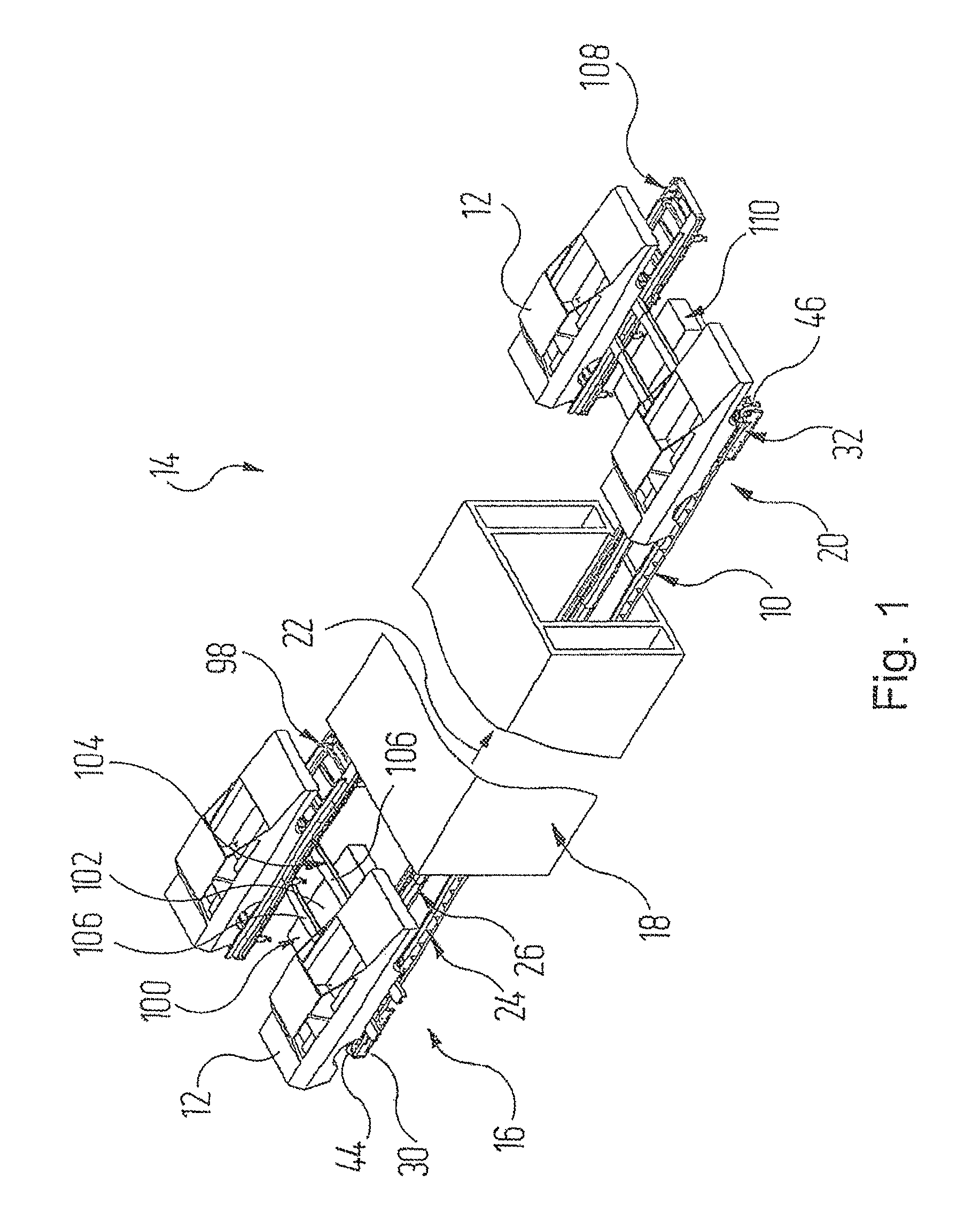
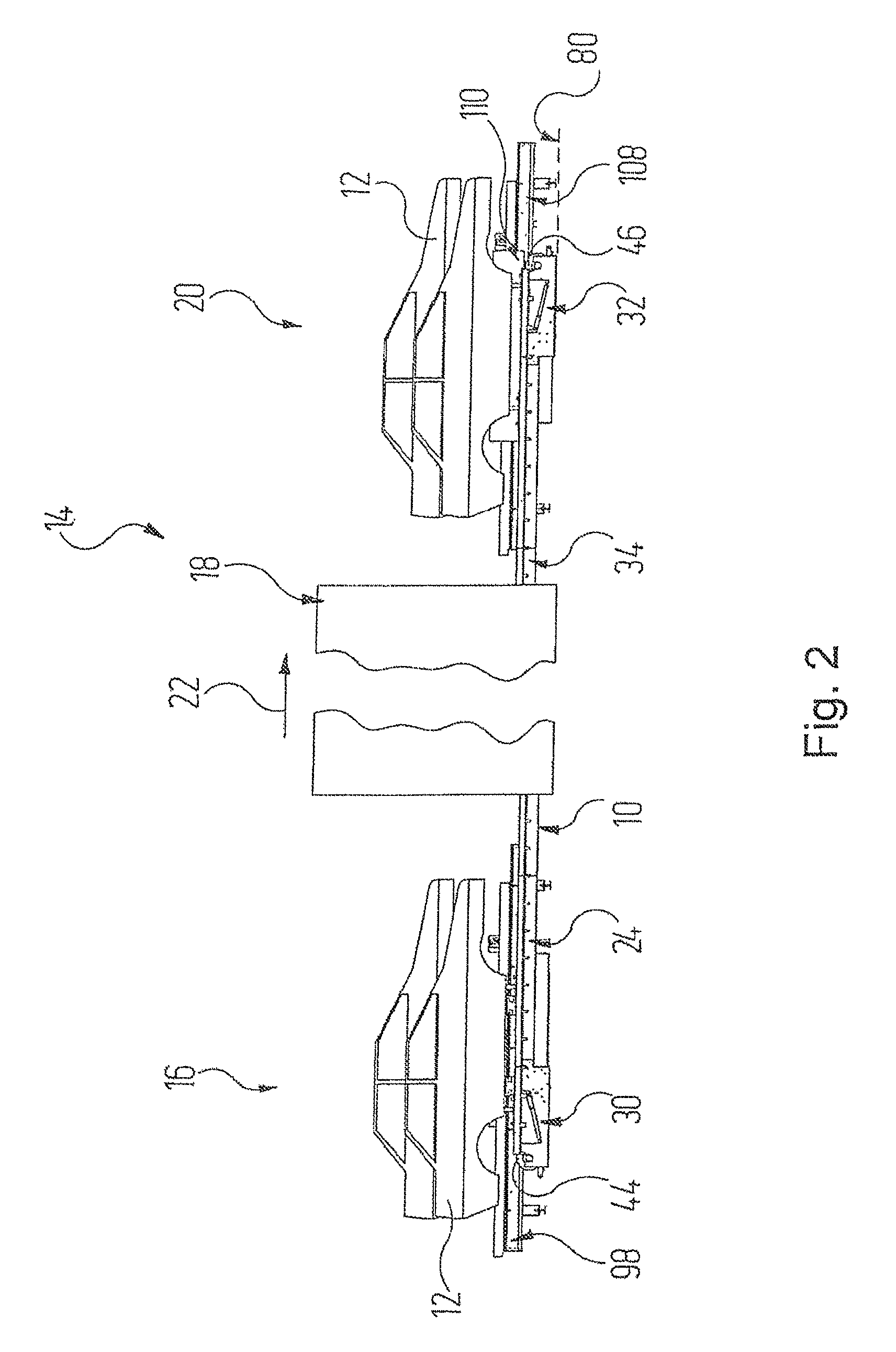
[0054]In the Figures, 10 denotes a supporting chain conveyor with the aid of which objects, which are indicated by way of example as vehicle bodies 12, are to be conveyed for example through a plant for surface treatment or through individual treatment zones of such a plant. By way of example, a drying zone 14 is shown, in which the vehicle bodies 12 or other objects (not shown here specifically) are conveyed from an entry region 16 through a drying tunnel 18 to an exit region 20. The vehicle bodies 12 are conveyed on the supporting chain conveyor 10 in the direction of the arrow 22, which is only shown in FIGS. ...


PUM


Abstract

An apparatus for conveying articles, in which at least one endless drive train forms a load-bearing strand and a return strand and specifies a conveying direction. A guide device for the at least one endless drive train includes a first deflecting element and at least one second deflecting element, over which the at least one endless drive train circulates. The at least one endless drive train carries along a plurality of supporting members which are arranged and configured such that they interact with supporting structures to which at least one article can be fastened. Furthermore, the at least one endless drive train carries along a plurality of coupling members which are arranged and configured such that they interact with standardized holding components of vehicle bodies. Also, a surface treatment plant having such a conveying apparatus.

Description

RELATED APPLICATIONS[0001]This application claims the filing benefit of International Patent Application No. PCT / EP2012 / 001907, filed on May 4, 2012, which claims the filing benefit of German Patent Application No. 10 2011 103 729.6, filed May 31, 2011, the contents of both of which are incorporated herein by reference.FIELD OF THE INVENTION[0002]The invention relates to a device for conveying objects having[0003]a) at least one continuous drive train, which forms a load-bearing strand and a return strand and specifies a conveying direction;[0004]b) a guide device for the at least one continuous drive train, which comprises a first deflecting element and at least one second deflecting element over which the at least one continuous drive train revolves,[0005]wherein[0006]c) the at least one continuous drive train carries along a plurality of supporting members which are arranged and configured such that they can cooperate with supporting structures to which at least one object can be...

Claims


Application Information

Patent Timeline
Patent Type & Authority Patents(United States)
IPC IPC(8): B65G15/14B65G37/00B65G47/00B65B35/24B62D65/18B65G17/00
CPCB65G15/14B62D65/18B65B35/24B65B35/243B65G17/002B65G37/00B65G37/005B65G47/00
Inventor ROBBIN, JOERG
Owner EISENMANN AG
Learn More