Device for preheating a fluid, notably a combustion engine coolant fluid

a technology for heating fluids and combustion engines, applied in engine starters, sustainable manufacturing/processing, lighting and heating apparatus, etc., can solve the problems of low heat exchange efficiency, low specific charge per cmsup>2 /sup>, and difficult placement on circuits to allow heat circulation. , to achieve the effect of reducing the loss at the atmosphere, increasing the efficiency of heat exchange, and optimizing the thermal yield

Active Publication Date: 2016-08-09
VOLANTE NINO
View PDF7 Cites 1 Cited by
  • Summary
  • Abstract
  • Description
  • Claims
  • Application Information

AI Technical Summary

Benefits of technology

[0015]The invention aims to provide a device for heating fluid that overcomes at least one of the above mentioned disadvantages. More particularly, the invention aims to provide a fluid heating device having an improved thermal performance and a simple and economical construction. More particularly, the invention seeks to provide a compact fluid heating device of simple and economical construction.Technical Solution
[0038]The steps of the invention have the advantage of optimizing the thermal yield, specifically by increasing the efficiency of heat exchange between the heating resistors and the fluid, and also by reducing losses at the atmosphere. Indeed, the construction of the heating body according to the invention allows an intimate contact with the fluid and with the resistors, and this in a very compact manner. The fluid passage may be dimensioned with a larger section which results in less pressure loss and increased efficiency. The open grooves of the heating body give a great modularity in respect of the number and / or size of the electrical resistors. This modularity is particularly advantageous to adapt the heating device for different applications. Indeed, one or more resistors can be connected to a voltage of 110 or 230 VAC (typically the home network) during the preheating of the engine of a vehicle at standstill. One or more additional resistors can be supplied with a voltage of 12 or 24 VDC provided by the vehicle battery to continue heating when the engine is running. The compact geometry of the heating body shape allows isolating easily by equipping it with an insulating cap. The latter may be provided detachably, which again is made easy by the optimized shape of the heating body.

Problems solved by technology

To reduce its size, the specific charge per cm2 is relatively high and therefore unreliable over time.
Performance thereof is very low and the placement on the circuit is not easy to allow the heat circulation.
For over a decade, motorists have significantly changed the design of water chambers in the engines and it becomes difficult to place this type of heaters, because this configuration does not allow creating effective circulation by the thermo siphon principle and heating properly and evenly engines.
However, the space needed is still too high to allow easy placement on intermediate vehicles (passenger cars, ambulances, trucks .
In addition, commonly used pumps must be positioned horizontally, which further reduces the possibilities of integration under the bonnet.
This would cause boiling of the fluid in the heating element that would result in a degradation of the shield thereof, and then this degradation would continue with premature rupture of the element.
The thermal connection between the resistors and the fluid is, however, not optimal.
In addition, the main body is subject to significant losses to the atmosphere.
The thermal efficiency of this device is therefore not optimal.
This device seems to work on the principle of thermo syphon, which limits the performance of heating.
This preheating device has the same disadvantage as the one of the above-mentioned document, i.e. that the thermal contact between the heating elements and the fluid is not optimized.
This device seems to work on the principle of thermo syphon, which limits the performance of heating.
Direct contact is not desirable for certain applications.
In addition, the overall size of the device is quite large and may cause integration problems.
This device seems to work on the principle of thermo syphon, which limits the performance of heating.
The power of heat exchange is limited in this teaching, especially due to the limited diameter of the bent pipe and the limited number of heating elements.
The power of heat exchange is very limited.
The power of heat exchange is limited in this teaching, especially due to the limited diameter of the bent pipe and the limited number of heating elements.

Method used


Image

  • Device for preheating a fluid, notably a combustion engine coolant fluid
  • Device for preheating a fluid, notably a combustion engine coolant fluid
  • Device for preheating a fluid, notably a combustion engine coolant fluid

Examples


Embodiment Construction

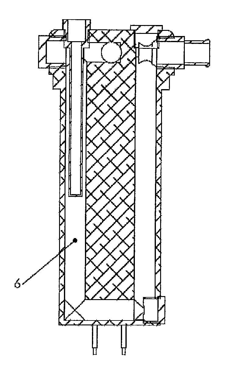
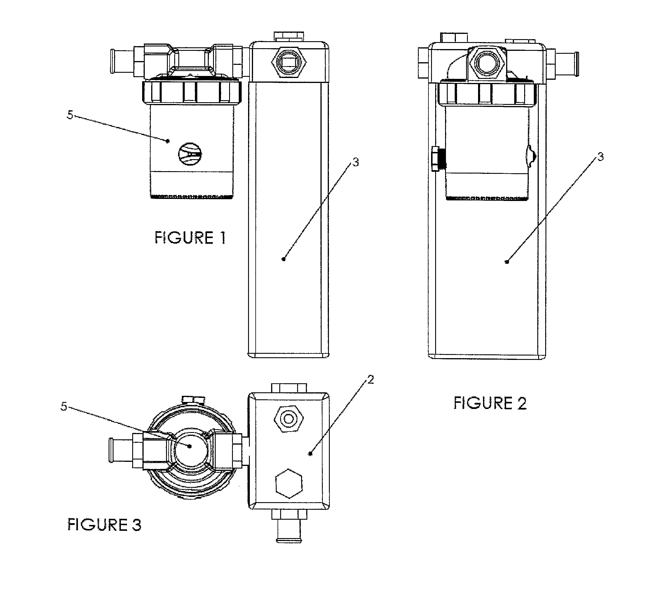
[0046]The fluid heating or preheating device shown in FIGS. 1 to 3 essentially comprises a heating body wrapped with an insulating cap 3 and a circulation pump 5. The heating body is generally elongated and has a generally rectangular section. It comprises a fluid inlet at its upper end, and an outlet disposed at the level of the inlet and oriented at about 90°, connected directly to the circulating pump 5.

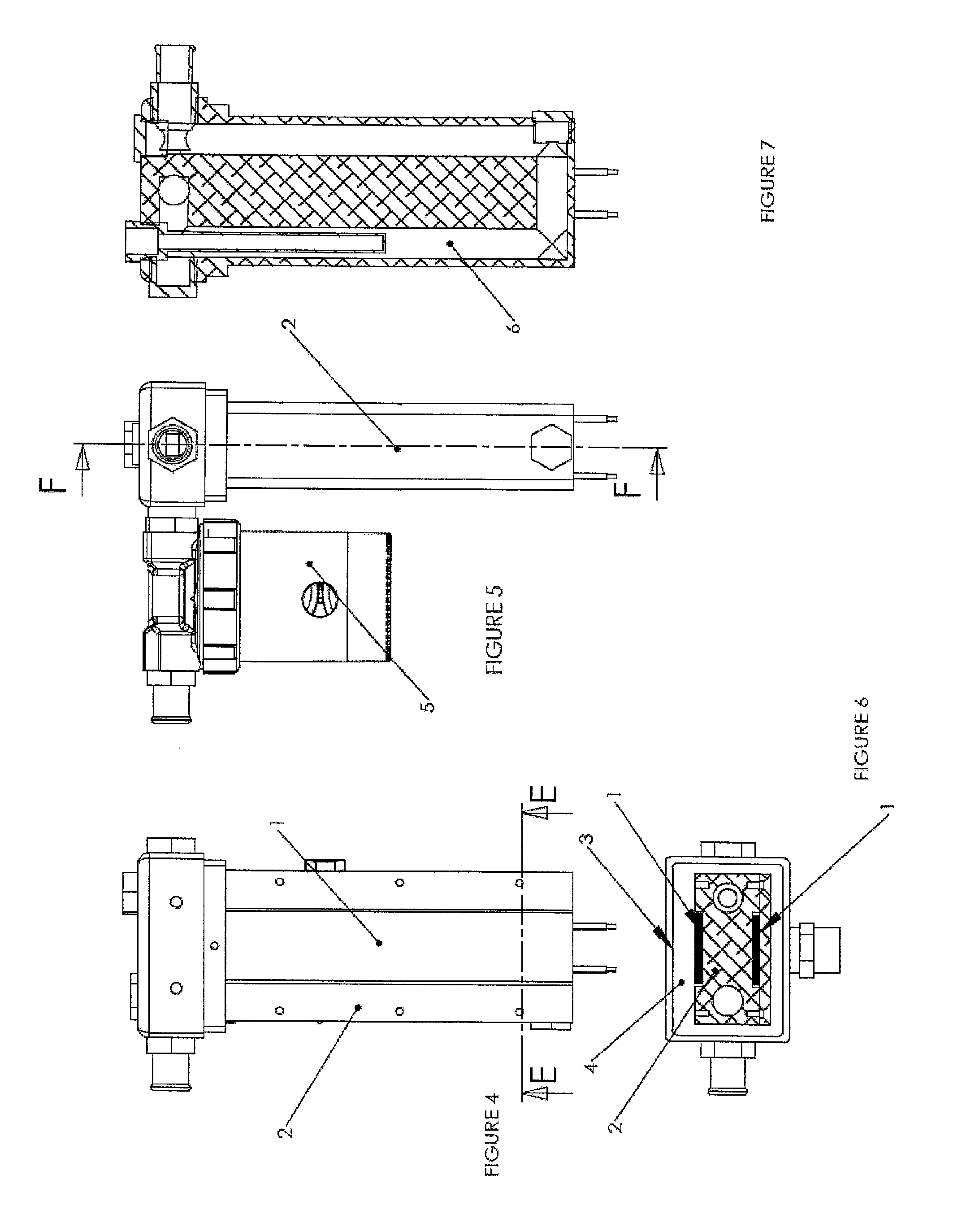
[0047]FIGS. 4-7 illustrate the body of the heating device, free of its insulation cap 3. It can be seen that it comprises a solid element 2 of a generally rectangular section and extending in length. This is preferentially a block made of a metallic heat conducting material such as aluminum. As is clearly visible in FIGS. 6 and 7, it is drilled on a large part of its length from its top face to near its bottom face, and this two times in two parallel directions. These two vertical drill holes are thus arranged near the ends of the rectangular section of the solid element. Each of ...


PUM


Abstract

The invention relates to a device for heating a fluid, essentially comprising a heating body with a solid element and one or more electric resistors of rectangular section of the PTC type which are arranged in grooves on the exterior surface of the solid element. The latter comprises a U-shaped passage for fluid. The invention also relates to a vehicle engine fitted with such a device for preheating or heating the coolant. The invention also relates to a method for preheating or heating using such a device.

Description

TECHNICAL FIELD[0001]The invention relates to a device for heating a fluid, in particular a fluid of a combustion engine, in particular a cooling fluid of such an engine. The present invention also relates to a method for heating fluid for many applications.[0002]The fluid can be sanitary water, chlorinated water, water / glycol, hydrocarbons (diesel, gasoline, oil, . . . ), vegetable oils (rapeseed), gas in liquid or gaseous state, . . . .[0003]Examples of heating applications are numerous: industrial, generators, cogeneration units, internal combustion engines (petrol, diesel, LPG, . . . ) pools, spas, hot water, aquariums, ponds, . . . .PRIOR ART[0004]The engines of emergency generators (hospitals, companies, . . . ) must be kept at an ideal temperature (±40° C.) for their immediate start, to ensure within a few seconds electricity supply in case of mains failure.[0005]The engine emergency vehicles (ambulance, fire brigade, . . . ) must be heated beforehand to ensure an immediate s...

Claims


Application Information

Patent Timeline
Patent Type & Authority Patents(United States)
IPC IPC(8): B60H1/03F24H1/12F02N19/10F02N19/02F01M5/02F02N19/04F01P11/20F28F7/02
CPCF24H1/121F02N19/10F01M5/021F01P11/20F02N19/02F02N19/04F28F7/02Y02P80/15Y02T10/12
Inventor CARLENS, JEAN-CLAUDEZUNE, JEAN-FRANÇOIS
Owner VOLANTE NINO
Why Eureka
Try Eureka