Automated fabrication of composite fillers

a composite filler and automatic technology, applied in the field of composite filler fabrication, can solve the problems of inability to meet the requirements of peak definition, time-consuming production technique, inadequate pre-conditioning, etc., and achieve the effects of smooth surface finish, good quality compaction, and improved dimensional control

Active Publication Date: 2016-08-16
THE BOEING CO
View PDF15 Cites 10 Cited by
  • Summary
  • Abstract
  • Description
  • Claims
  • Application Information

AI Technical Summary

Benefits of technology

[0010]The disclosed embodiments provide a method and apparatus of producing composite radius fillers suitable for use in high-performance composite structures. The radius fillers are produced using a continuous pultrusion process in which prepreg composite tape is pulled through one or more for

Problems solved by technology

Radius fillers may be fabricated by hand, however this production technique is time consuming, labor intensive and may yield radius fillers that are inconsistent, and/or do not meet required specifications.
However, these automated radius filler machines are not currently capable of producing radius fillers to stringent specifications for peak definition, even ply transitions, symmetry and the absence of loose fibers.
These deficiencies are caused, in part, by inadequate pre-conditioning and/or poor forming die design.
Further

Method used


Image

  • Automated fabrication of composite fillers
  • Automated fabrication of composite fillers
  • Automated fabrication of composite fillers

Examples


Embodiment Construction

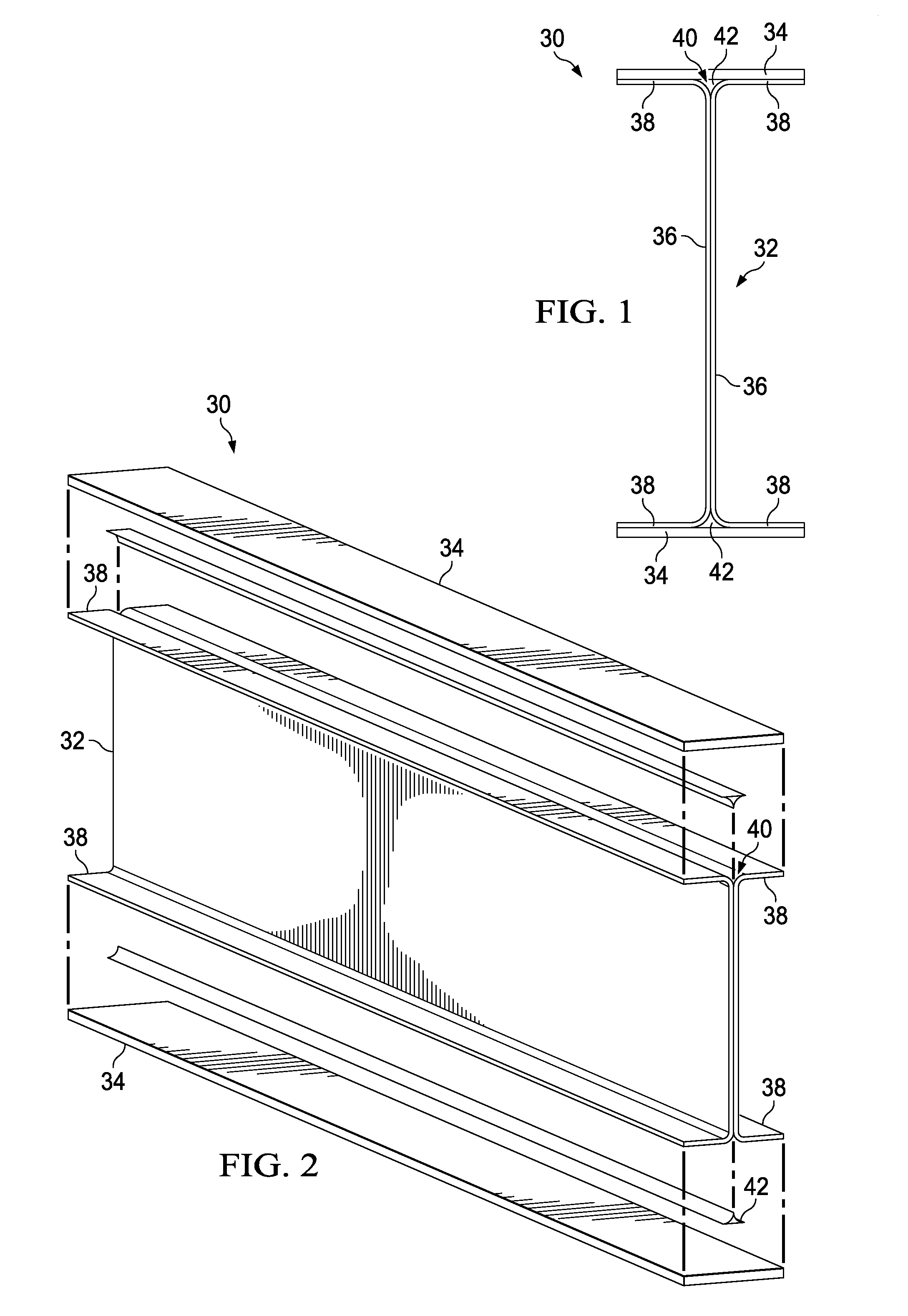
[0045]The disclosed embodiments relate to a method and apparatus for producing high-performance composite fillers, sometimes referred to hereinafter as “radius fillers”, The radius fillers may be used to strengthen primary composite structures and assemblies, such as the composite laminate I-beam 30 shown in FIGS. 1, 2 and 3. The I-beam 30 comprises upper and lower composite laminate caps 34 joined by a web 32. The I-beam 30 may be produced by joining a pair of C-shaped, composite laminate members 36 having outwardly turned flanges 38, each of which transitions to the web 32 through a radiused corner 46.

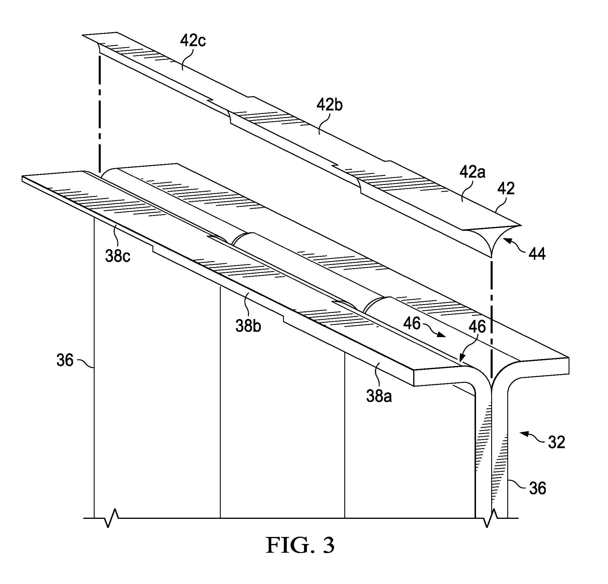
[0046]The area between adjacent radius corners 46 and a cap 34 forms a void 40 that may be filled by a radius filler 42 produced in accordance with the disclosed embodiments described below. In the illustrated embodiment, the gauge or thickness of the C-shaped members 36 varies along its length, consequently, different sections 38a, 38b, 38c of the flanges 38 have differing thickness...


PUM

PropertyMeasurementUnit
Gravityaaaaaaaaaa

Abstract

A composite radius filler having a varying cross-sectional shape is pre-conditioned before being pultruded through forming dies. The composite filler radius filler includes a tab ply having a varying width that is laminated onto a supporting, full width base ply.

Description

CROSS REFERENCE TO RELATED APPLICATIONS[0001]This application is related to co-pending U.S. patent application Ser. No. 14 / 045,195, filed concurrently herewith on Oct. 3, 2013, which is incorporated by reference herein in its entirety.BACKGROUND INFORMATION[0002]1. Field[0003]The present disclosure generally relates to the fabrication of composite structures, and deals more particularly with a method and apparatus for automated fabrication of composite fillers used to fill a cavity between assembled composite members.[0004]2. Background[0005]Assembled composite structures sometimes contain cavities that must be filled in order to maximize the strength and / or rigidity of the structure. For example, two or more composite members with radiused edges may be assembled together such that their adjacent radiused edges form a radiused cavity. In order to fill the cavity and strengthen the structure, a pre-formed radius filler is placed in the cavity and bonded to the members.[0006]Fillers, ...

Claims


Application Information

Patent Timeline
IPC IPC(8): B32B38/00
CPCB32B38/0012Y10T156/1008B29C70/52B32B38/0004B32B38/10B32B2305/076B32B2605/18B29C70/526B29D99/0007B29D99/0005B29C65/70
Inventor SUTKUS, DONALD J.HALLMAN, SANDIE H. CHEUNGFIX, COURTNEY M.MCCARVILLE, DOUGLAS A.
Owner THE BOEING CO
Why Eureka
Try Eureka