Method for manufacturing a wind turbine rotor blade

a manufacturing method and technology for wind turbines, applied in the manufacture of final products, machines/engines, other domestic articles, etc., to achieve the effect of simplifying the manufacturing method of wind turbine blades

Active Publication Date: 2016-08-23
SIEMENS GAMESA RENEWABLE ENERGY AS
View PDF17 Cites 1 Cited by
  • Summary
  • Abstract
  • Description
  • Claims
  • Application Information

AI Technical Summary

Benefits of technology

[0006]It may be an object of the present invention to simplify a manufacturing method for a wind turbine blade.
[0017]By the present invention a mould dorn to which composite fibre layers are placed in the prior art manufacturing methods may be obsolete and a hollow component, such as the blade of wind turbine, may be manufactured in one step. This is achieved by fixing (securing) the collapsed bag and the first composite fibre layer to the first mould element. The fixing of the bag and the first composite fibre layer may be achieved by applying an adhesive (e.g. resin) or by providing underpressure between the bag and the first mould surface. Hence, when the bag and the first composite fibre layer is fixed to the mould surface, the first mould element may be handled very simple and no slipping and relative movement of the first composite fibre layer with respect to the first mould surface is caused, because the first composite fibre layer is pressed on the first mould surface by the bag. For this reason, the first mould element may be turned overhead without a falling-out of the bag and the first composite fibre layer out of the first mould element. Hence, the first mould element and the second mould element may be assembled easily and later after a coupling of both mould elements, finalizing steps, such as resin injection or curing may be applied for finalizing the profile of the component to be formed.
[0019]Additionally, after curing the composite fibre layers, the bag may be collapsed and thus reduced in size again, so that the bag may easily be removed from the inner cavity of the manufactured hollow component.
[0022]According to a further exemplary embodiment, the first composite layer is larger than the first mould surface such that the first composite fibre layer forms a surplus section that extends over an edge of the first mould surface. The surplus section describes an excess length, an overhang or a protrusion. By using a surplus section in particular at the margin areas of the first composite fibre layer, an overlapping of the second composite fibre layer over the edges of the mould element, which edges defines the area of the first mould surface corresponds to a size of a respective profile section, may be achieved. The surplus section is movable (e.g. foldable) and is not fixed to the first mould surface by the bag.
[0023]According to a further exemplary embodiment, the coupling of the first mould element to the second mould element comprises an adjusting of the first mould element to the second mould element in such a way, that the surplus section overlaps partially with the second composite fibre layer in the second mould element. Hence, the contact areas (interface sections) between the first composite fibre layer and the second composite fibre layer may be reinforced, so that a more robust component may be manufactured. Thereby, during the adjustment of the first mould elements to the second mould elements, the surplus section is bended to the inside into a cavity formed between the coupled mould elements, so that the surplus section overlaps with the second composite fibre layer.
[0048]When the bag is unfolded and inflated, an underpressure (vacuum) may be applied to the space between the first mould surface, the second mould surface and the bag, so that by resin injection, resin is injected to the first composite fibre layer and the second composite fibre layer. Finally, curing and casting of the hollow components may be accomplished and the finished hollow component may be removed easily from the mould elements.

Problems solved by technology

After curing of the fibre layers in the mould parts, the mould core has to be removed, which may cause difficulties due to the large size of the wind turbine blades and due to the complex profiles of the wind turbine blades.

Method used


Image

  • Method for manufacturing a wind turbine rotor blade
  • Method for manufacturing a wind turbine rotor blade
  • Method for manufacturing a wind turbine rotor blade

Examples


Embodiment Construction

[0057]The illustrations in the drawings are schematical. It is noted that in different figures, similar or identical elements are provided with the same reference signs.

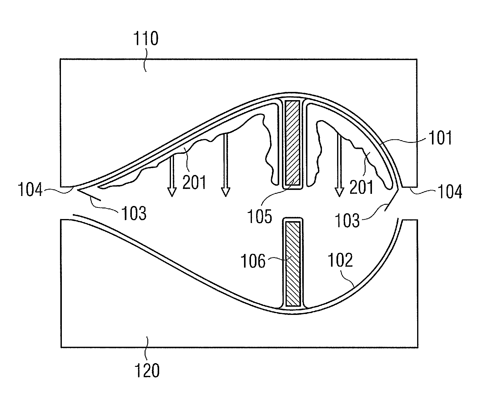
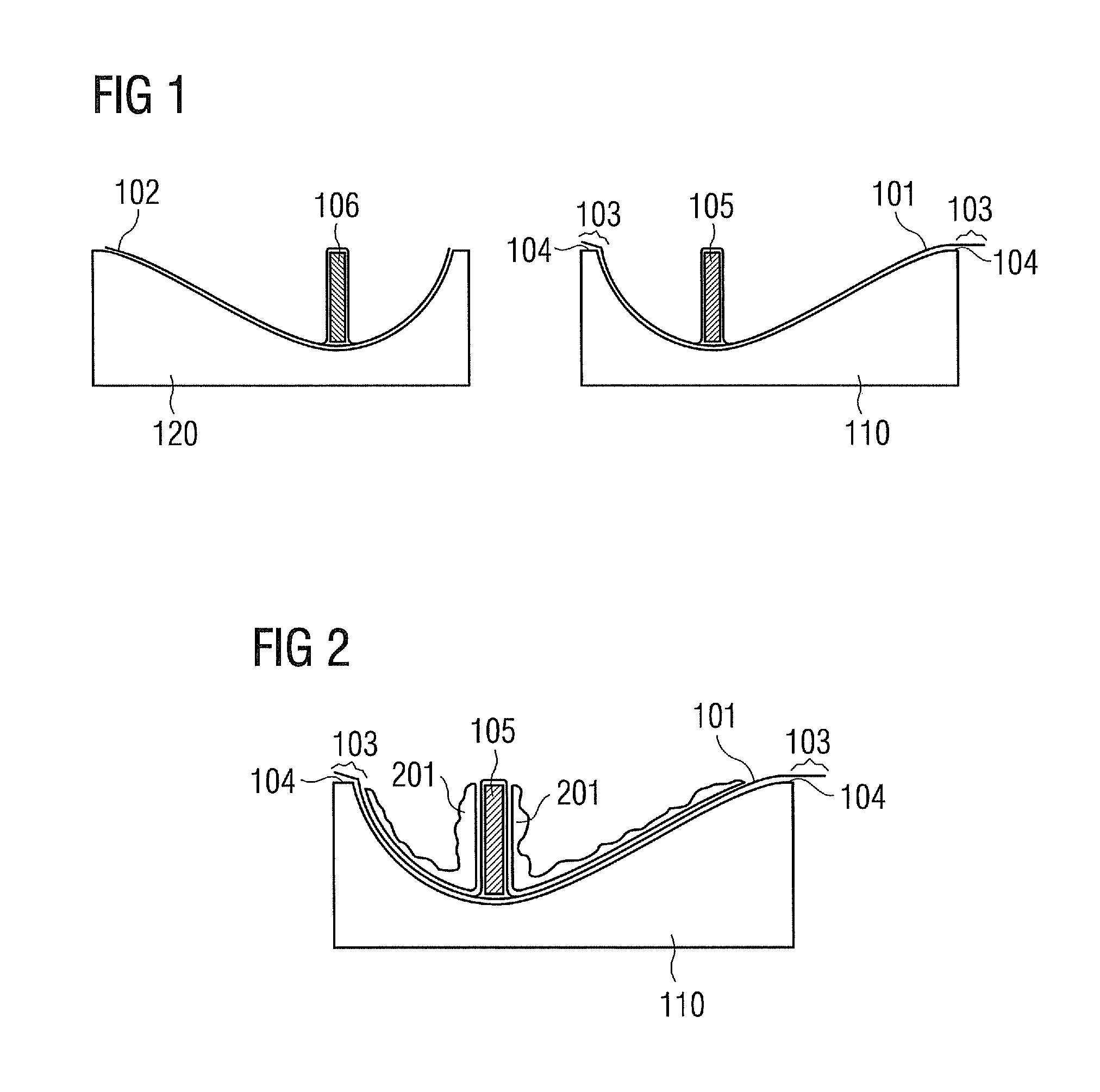
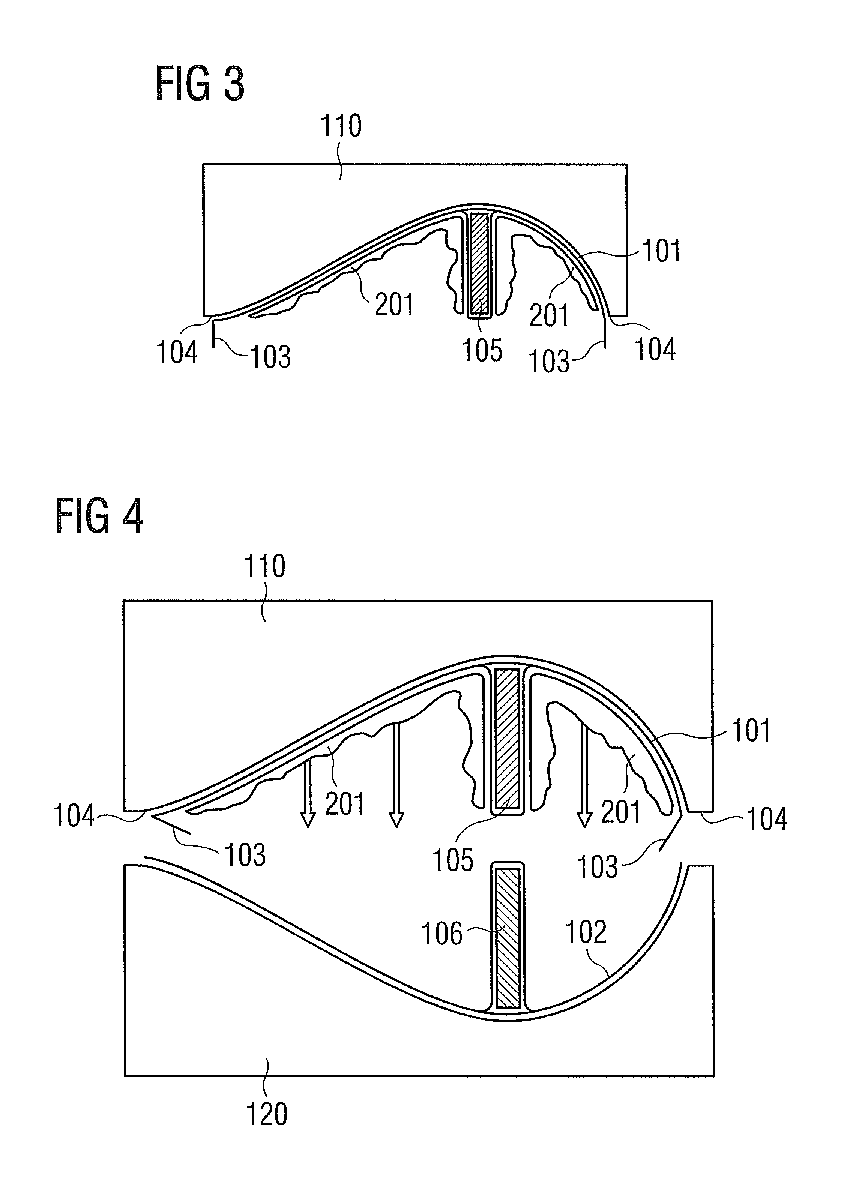
[0058]In FIG. 1 to FIG. 5, a method for forming a profile for manufacturing a hollow component made of composite fibre, in particular a hollow blade for a wind turbine, is shown.

[0059]FIG. 1 shows a first mould element 110 and a second mould element 120. To a first mould surface of the first mould element 110 a first composite fibre layer 101 is laid out. The first mould surface corresponds to a first profile section of the hollow component to be manufactured. For example, the hollow component is a blade of a wind turbine, so that the first profile section may form a (upper) half of the blade to be manufactured.

[0060]A second composite fibre layer 102 may be laid out onto a second mould surface of the second mould element 120, wherein the second mould surface corresponds to a second profile section of the hollow comp...


PUM

PropertyMeasurementUnit
gravityaaaaaaaaaa
sizeaaaaaaaaaa
flexibleaaaaaaaaaa

Abstract

A method for forming a profile for a hollow component is provided. A first composite fiber layer is laid out on a first surface corresponding to a first profile section of the component. A second composite fiber layer is laid out in a second surface corresponding to a second profile section of the component. A collapsed bag is laid out in onto the first composite fiber layer. The bag and the first composite fiber layer are fixed to the first surface. First and second mould elements are coupled such that the first surface and the second surface correspond to the first and second profiles. The bag is inflated such that the first composite fiber layer is pressed to the first surface and the second composite fiber layer is pressed to the second surface so that the first and second layers are coupled to form the profile.

Description

CROSS REFERENCE TO RELATED APPLICATION[0001]This application claims priority of European Patent Office application No. 10187414.7 EP filed Oct. 13, 2010, which is incorporated by reference herein in its entirety.FIELD OF INVENTION[0002]The present invention relates to a method for forming a profile for manufacturing a hollow component made of composite fibre, in particular of a hollow blade for a wind turbine. Moreover, the present invention relates to a blade for a wind turbine and to a moulding system.ART BACKGROUND[0003]Wind turbine blades for wind turbine becoming larger and larger in size. Hence, modern wind turbine blades are mostly made of composite fibre, in particular made of glass fibre. In order to manufacture such large wind turbine blades, several manufacturing methods, such as resin transfer moulding, are applied.[0004]EP 1 310 351 A1 discloses a method for manufacturing blades for a wind turbine. A mould core is placed to a layer of glass fibre, which is laid in a mou...

Claims


Application Information

Patent Timeline
Patent Type & Authority Patents(United States)
IPC IPC(8): B29C70/44F03D1/06B29L31/08
CPCB29C70/443B29C70/446F03D1/0675B29L2031/085F05B2230/00Y02E10/722Y02E10/721Y02P70/523B29D99/0028Y02E10/72Y02P70/50B29C43/56B29C70/44
Inventor SCHIBSBYE, KARSTEN
Owner SIEMENS GAMESA RENEWABLE ENERGY AS
Why Eureka
Try Eureka