Reverse circulation fluidized bed reactor for granular polysilicon production

a technology of fluidized bed reactor and polysilicon, which is applied in the direction of silicon compounds, coatings, chemistry apparatuses and processes, etc., can solve the problems of affecting process and product quality, dust formation, and the reaction gas molecules can spontaneously decompose, so as to minimize the production of silicon dust, reduce the hydrogen content, and minimize the effect of silicon deposition

Active Publication Date: 2016-08-30
ADVANCED MATERIAL SOLUTIONS LLC
View PDF20 Cites 1 Cited by
  • Summary
  • Abstract
  • Description
  • Claims
  • Application Information

AI Technical Summary

Benefits of technology

[0011]A fluidized bed reactor (FBR) with reverse flow minimizes production of silicon dust, minimizes deposition of silicon on the walls, heaters, and zone dividers, and produces silicon product with reduced hydrogen content, so that a separate dehydrogenation step is not needed. The reactor provides a pre-reaction heating gas flow that lifts the particles of polysilicon upward through the pre-reaction heating zone, so that they enter the reaction zone and first encounter the reaction gas at the top of the reaction zone, rather than at the bottom. The flow of reaction gas is relatively weaker, so as to allow the particles to slowly settle through the reaction zone and re-enter the bottom of the pre-reaction heating zone. As a result, the circulation of the silicon particles through the reactor is reversed as compared to conventional internally circulating FBR's.
[0012]Because the pre-reaction gas velocity is higher than the reaction gas velocity, there is little, if any, leakage of reaction gas into the pre-reaction heating zone, thereby minimizing dust formation and deposition of silicon on the walls within the pre-reaction heating zone.
[0013]Because the particles are relatively hotter at the top of the reaction zone and cooler at the bottom of the reaction zone, the reaction gas is also hotter at the top of the reaction zone, where the silicon concentration is lowest, and cooler at the bottom of the reaction zone, where the concentration of silicon is highest. As a result, formation of dust due to heating of the reaction gas is reduced, and silicon deposition by the reaction gas onto the walls of the reaction zone is minimized.
[0014]In embodiments, the at least one vertical separator that separates the pre-reaction heating zone from the reaction zone is thermally insulating, so that heating of the walls of the reaction zone is reduced, and the temperature of the walls is minimized. This further reduces deposition of silicon onto the walls of the reaction zone. In some of these embodiments, the vertical separator is either made from an insulating material or filled with an insulating material. In other embodiments, the vertical separator includes double walls separated by an evacuated or gas-filled space.

Problems solved by technology

However, several problems still exist which affect the process and product quality.
One of these problems is dust formation.
As a result, molecules in the reaction gas can spontaneously decompose, forming very fine particles of silicon “dust.” Dust formation in an FBR reactor is not only a waste of silicon, but is also hard to handle, due to its low density.
When attached to the surfaces of the silicon product particles, dust also degrades the quality of the silicon product.
Another problem in conventional FBR reactors is deposition of the reaction gas on the vertical separator 102 and / or the walls of the FBR chamber 100.
A third problem with conventional FBR reactors is the high concentration of hydrogen typically found in the granular polysilicon product.
Hydrogen trapped within and / or adsorbed onto the surface of product silicon particles can result in bubbles in the melting process downstream, which can be detrimental to the quality of ingots or crystals grown from the melt.
However, this approach requires a separate process and separate equipment, which makes the process more complex, and increases both the capital and operating costs.
Unfortunately, due to the higher flow rate of the reaction gas, which carries the particles upward, as compared to the pre-reaction fluidizing gas, which allows the particles to drift downward, it is inevitable that some of the reaction gas will also flow over or under the vertical separator 102 and thereby enter into the pre-reaction heating zone, where it will readily form silicon dust and deposit silicon on the heated walls.

Method used


Image

  • Reverse circulation fluidized bed reactor for granular polysilicon production
  • Reverse circulation fluidized bed reactor for granular polysilicon production
  • Reverse circulation fluidized bed reactor for granular polysilicon production

Examples


Embodiment Construction

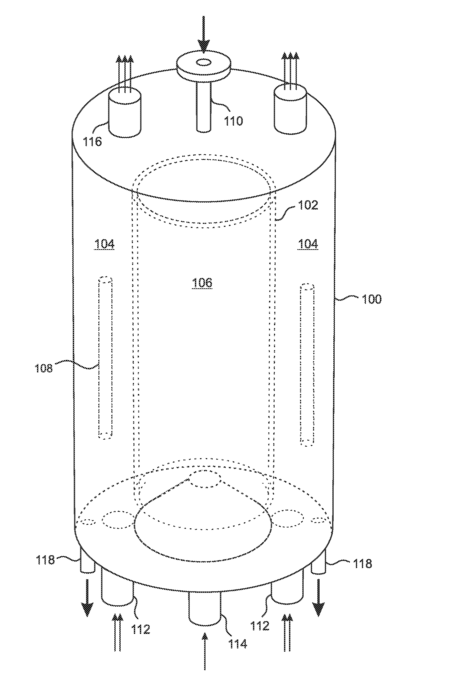
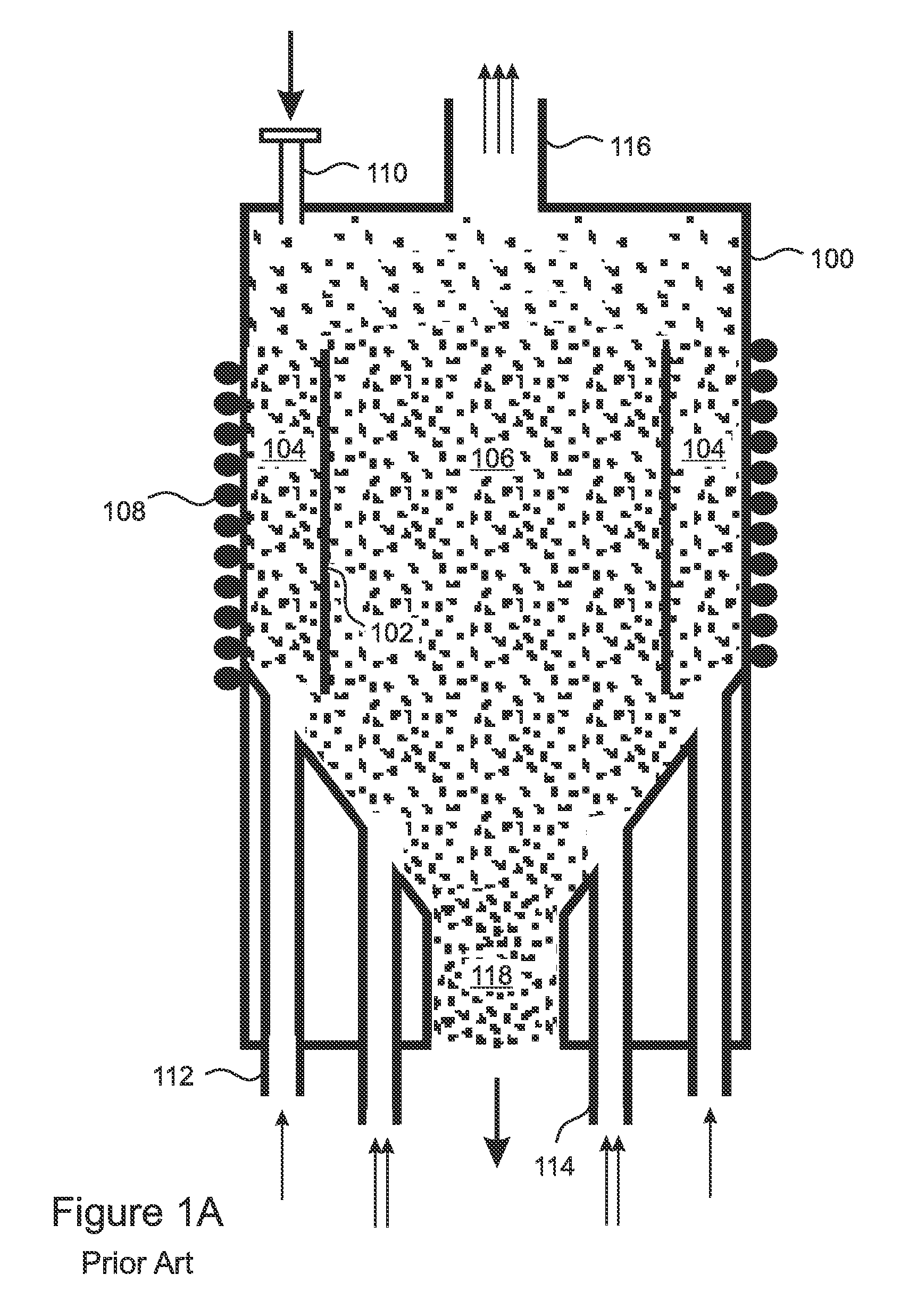
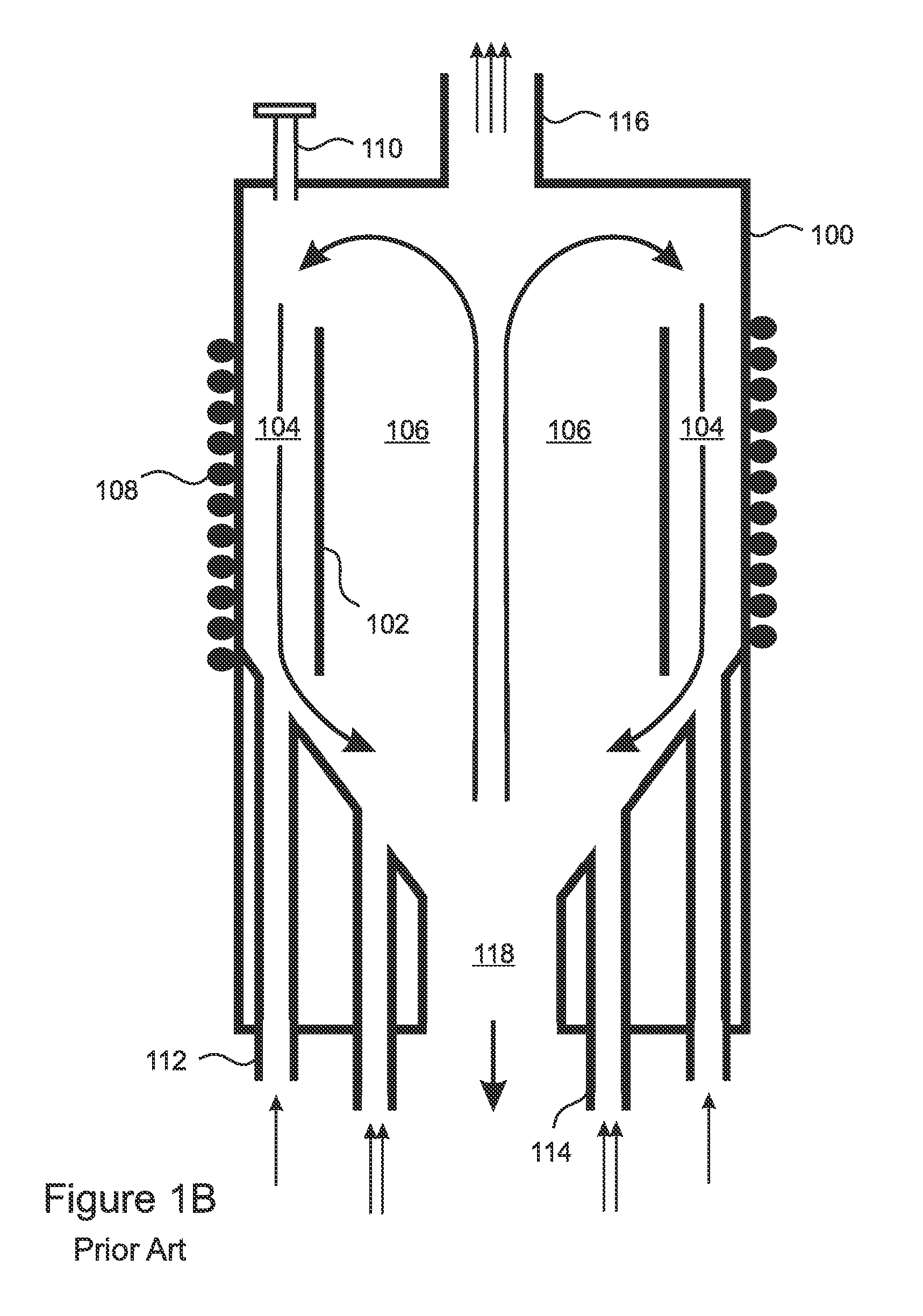
[0043]The present invention is a reverse internally circulating fluidized bed reactor (FBR) that minimizes production of silicon dust, minimizes deposition of silicon on the walls and zone dividers, and produces silicon product with reduced hydrogen content, so that a separate dehydrogenation step is not needed after the silicon product is removed from the reactor. The reactor provides a pre-reaction heating gas flow that is able to lift particles of polysilicon upward through the pre-reaction heating zone, so that they enter the reaction zone and first encounter the reaction gas at the top of the reaction zone. The flow of reaction gas is relatively weaker, so that the particles slowly settle through the reaction zone and re-enter the bottom of the pre-reaction heating zone. As a result, the circulation of the silicon particles through the present invention is reversed as compared to conventional internally circulating FBR's.

[0044]A cylindrical embodiment of the present invention i...


PUM

PropertyMeasurementUnit
temperatureaaaaaaaaaa
velocityaaaaaaaaaa
velocitiesaaaaaaaaaa

Abstract

A reverse fluidized bed reactor (FBR) is separated by a thermally insulating vertical divider into a pre-reaction heating zone, a reaction zone, and a dehydrogenation zone. The dehydrogenation zone can be distinct, or the heating zone can serve as the dehydrogenation zone. Particles of polysilicon circulate upward through the heating zone and into the top of the reaction zone, where deposition of silicon occurs, and the grown particles slowly settle until they reenter the bottom of the pre-reaction heating zone. Dust formation, wall deposition, and hydrogen content in the product silicon particles are thereby minimized.

Description

FIELD OF THE INVENTION[0001]The invention relates to reactors for producing polysilicon, and more particularly, to fluidized bed reactors for producing polysilicon.BACKGROUND OF THE INVENTION[0002]Manufacturing polysilicon through chemical vapor deposition of silicon in a fluidized bed reactor (FBR) has advantages over the traditional Siemens process, which decomposes silane or chlorosilane onto silicon “slim” rods in a bell-jar reactor. With reference to FIG. 1A, which shows a specific design of one type of FBR reactor, at least one divider 102 divides a reactor chamber 100 into a pre-reaction heating zone 104 and a reaction zone 106. In the specific example of FIG. 1A, the divider is a cylindrical, vertical divider 102 so that the zones 104, 106 are concentric. Small “seed” particles of polysilicon are introduced through a particle inlet port 110 into the pre-reaction heating zone 104, where they are heated by a heater 108 to a temperature above the silicon deposition temperature ...

Claims


Application Information

Patent Timeline
Patent Type & Authority Patents(United States)
IPC IPC(8): C23C16/442C23C16/24C01B33/027C23C16/44C23C16/52
CPCC23C16/4417C01B33/027C23C16/52C23C16/442C23C16/24
Inventor CHINN, WENJUN LFAHRENBRUCK, F. SCOTTSKINNER, SHAWN DMORAN, LAURA EGUM, JEFFREY C.
Owner ADVANCED MATERIAL SOLUTIONS LLC
Why Eureka
Try Eureka