Accumulator for a cooling fluid and heat exchanger

a technology of heat exchanger and cooling fluid, which is applied in the direction of sealing, lighting and heating apparatus, caps, etc., can solve the problems of only being able to design a u flow field and relatively large expenditure in manufacture or assembly, and achieve the effect of improving the heat exchanger

Active Publication Date: 2016-08-30
MAHLE INT GMBH
View PDF16 Cites 4 Cited by
  • Summary
  • Abstract
  • Description
  • Claims
  • Application Information

AI Technical Summary

Benefits of technology

[0008]Advantageously the accumulator can be produced with simple means of production and few manufacturing steps in a cost-effective and rapid manner. This results in a reduction of design-, manufacture-, and assembly expenditure. Moreover this results in a lower weight and less manufacturing waste.
[0009]In this manner the construction for example of a modular tube heat exchanger is considerably facilitated in particular with respect to the implementation of a U flow field.
[0016]The floor can have an aperture that is arranged between the first interface and the further interface. The projection of the lid can be embodied in such a way as to engage in the aperture of the floor. The aperture can be shaped in accordance with the apertures of the interfaces. A uniform tool for the production can be used thereby. If the projection of the lid engages in the aperture, the lid can be secured against slipping.
[0017]Alternatively the floor can have a contact area between the interface and the further interface and the projection of the lid can be embodied in such a way as to bear against the contact area in a fluid-tight manner. Without an aperture, the floor can be embodied in a more stable and compact manner.
[0021]The floor can be connected to the lid via a soldered connection. A durable tight connection of the two components can be achieved thereby.

Problems solved by technology

However, the design of a U flow field is only possible with a relatively large expenditure with respect to manufacture or assembly.

Method used


Image

  • Accumulator for a cooling fluid and heat exchanger
  • Accumulator for a cooling fluid and heat exchanger
  • Accumulator for a cooling fluid and heat exchanger

Examples


Embodiment Construction

[0035]In the following description of the preferred exemplary embodiments of the present invention, the same or similar reference numbers are used for the elements shown in the various drawings and acting in a similar manner, wherein a repeated description of these elements is omitted.

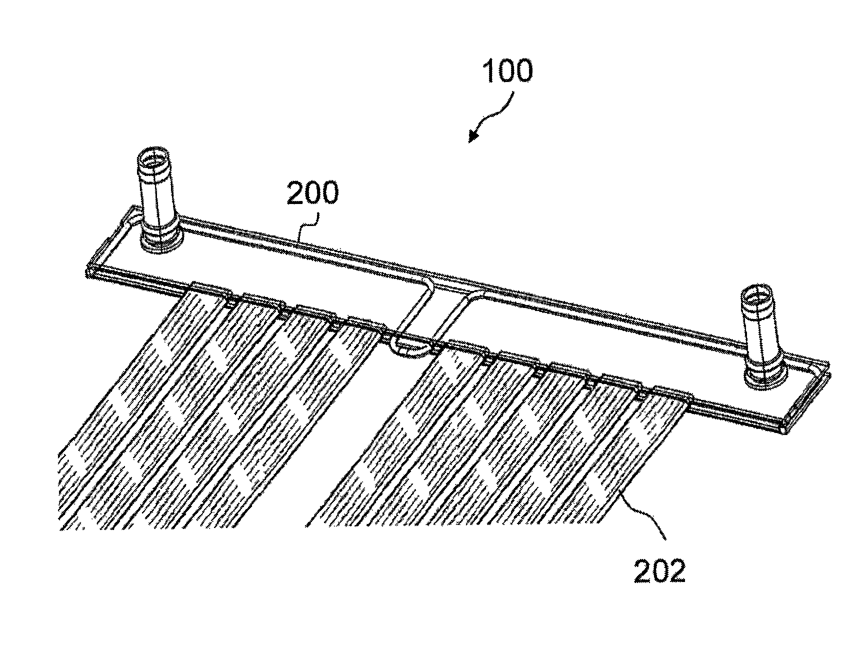
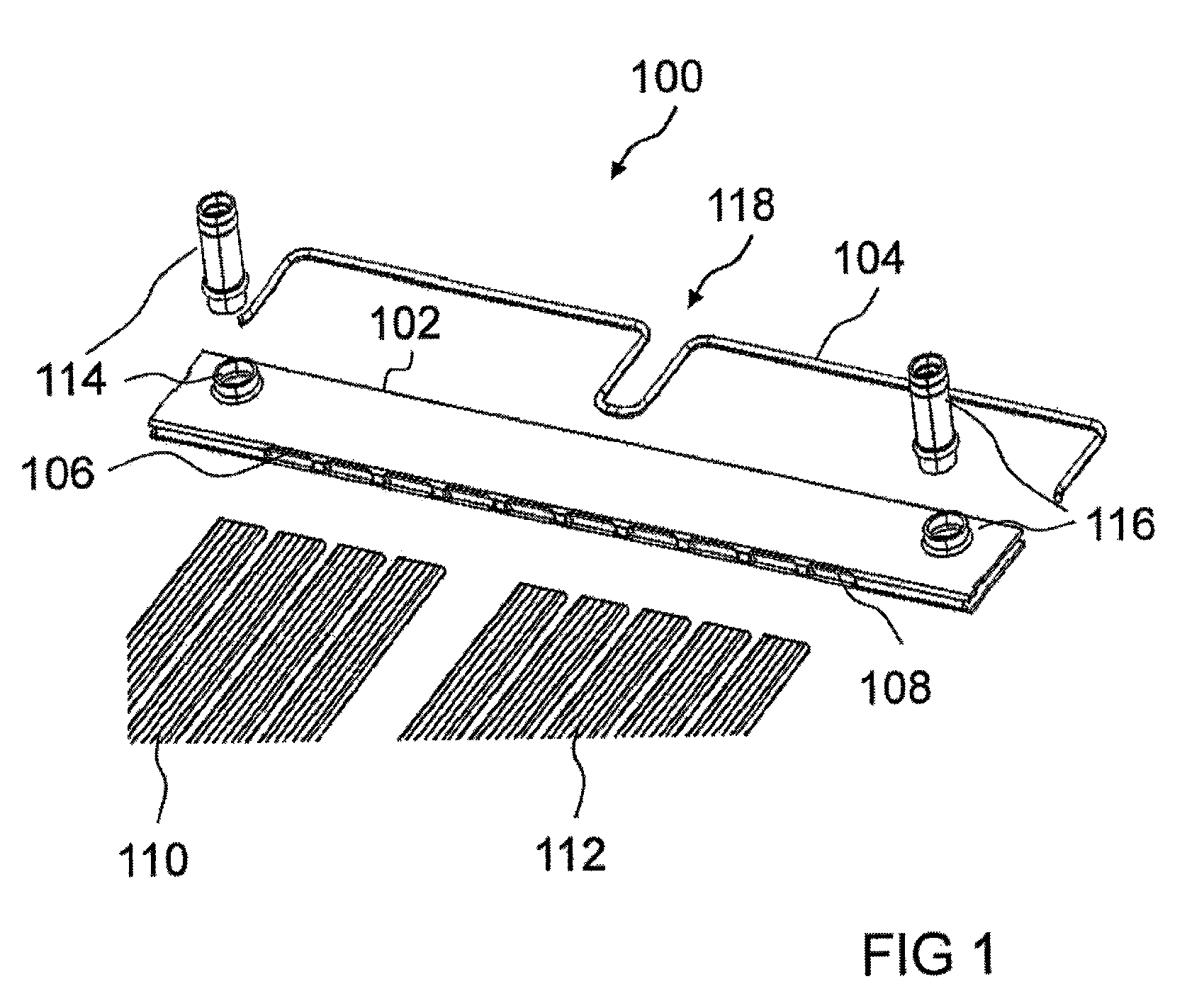
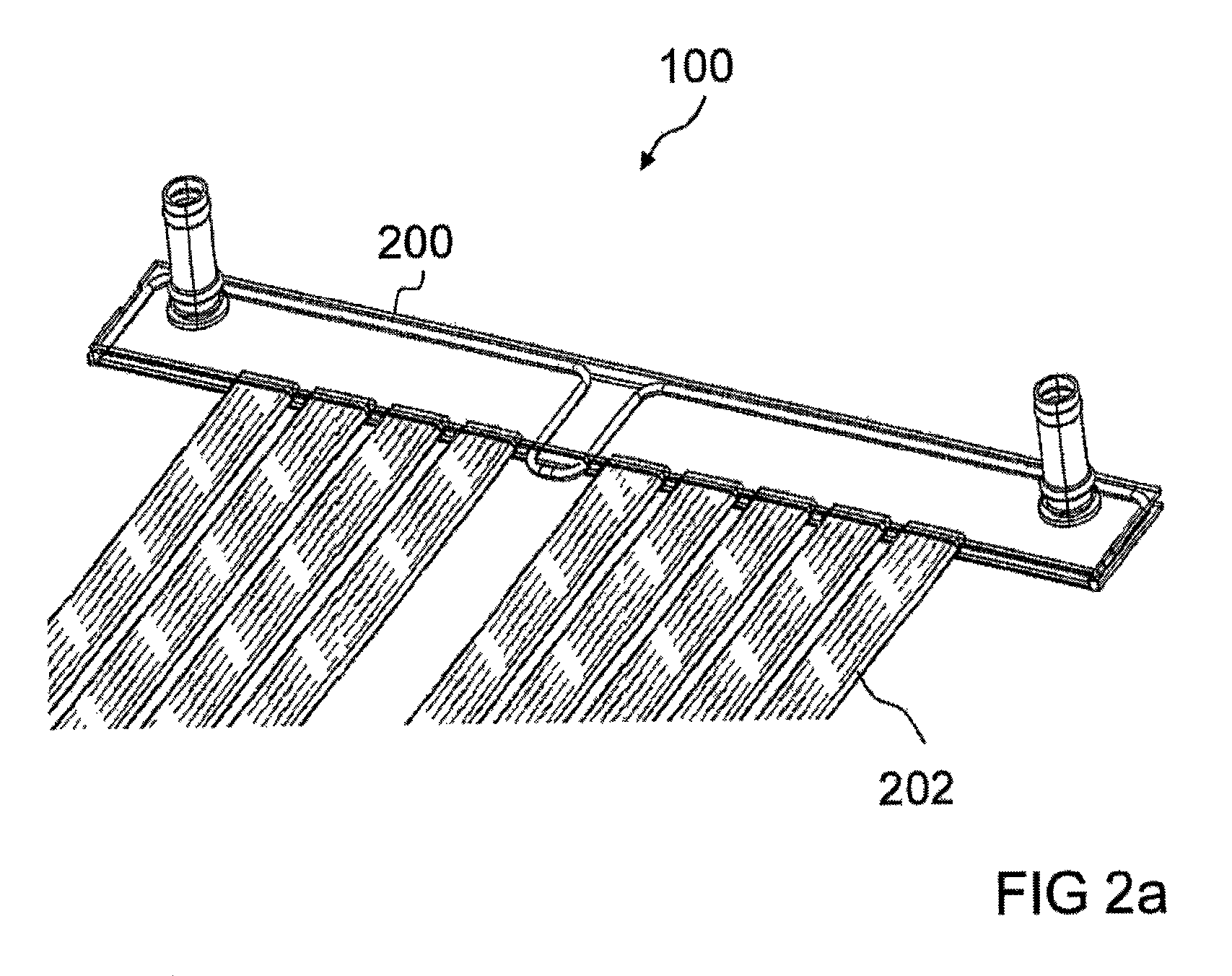
[0036]FIG. 1 shows an exploded view of a heat exchanger 100 according to an exemplary embodiment of the present invention. Components of an accumulator of the heat exchanger 100 and components of a cooling area of the heat exchanger 100 are shown. The accumulator has a floor 102 and a lid 104.

[0037]The floor 102 is embodied as a stamping / bending part made of plate material. It has a U-shaped contour. A first arm of the U-shaped floor 102 is oriented parallel to a second equally long arm of the U-shaped floor 102. A first interface 106 and a second interface 108 are arranged along a bending edge of the floor 102, at which the first arm of the floor 102 is connected to the second arm of the floor 102. Th...


PUM


Abstract

An accumulator for a cooling fluid is provided that includes a floor. The floor has an interface for connecting a chamber of the accumulator to at least one cooling tube. The floor also has an opening that extends at least over a partial area of the chamber. The accumulator furthermore has a lid that is embodied in such a way as to seal the opening of the floor in a fluid-tight manner. The lid is embodied as wire or extrusion profile.

Description

[0001]This nonprovisional application claims priority under 35 U.S.C. §119(a) to German Patent Application No. DE 10 2011 079 091.8, which was filed in Germany on Jul. 13, 2011, and which is herein incorporated by reference.BACKGROUND OF THE INVENTION[0002]1. Field of the Invention[0003]The present invention relates to an accumulator for a cooling fluid as well as to a heat exchanger.[0004]2. Description of the Background Art[0005]In modern heat exchanger applications, in particular for heat exchangers for hybrid- and electric vehicle accumulator systems, ever greater demands are made with respect to weight, costs and construction space. This requires new variants in these fields of application in both the design and the production of heat exchangers, which variants meet these demands. Up to now cooling plates in a layer sheet metal construction, also other constructions such as two-layer cooling plates or modular tube cooling plates have been usual. Depending on the design, the hea...

Claims


Application Information

Patent Timeline
Patent Type & Authority Patents(United States)
IPC IPC(8): F28F9/02
CPCF28F9/02F28F9/0209F28F9/0224F28F9/0212
Inventor HIRSCH, STEFANNEFF, HEIKOWIEBELT, ACHIM
Owner MAHLE INT GMBH
Why Eureka
Try Eureka