Interventional MR imaging with motion compensation

a technology of motion compensation and mr image, applied in the field of mr imaging, can solve the problems of different kinds of blurring, motion artifacts in the respective reconstructed mr image, motion artifacts, etc., and achieve the effects of improving the accuracy of treatment, high temporal resolution, and detecting local motion

Active Publication Date: 2016-08-30
KONINKLIJKE PHILIPS ELECTRONICS NV
View PDF9 Cites 2 Cited by
  • Summary
  • Abstract
  • Description
  • Claims
  • Application Information

AI Technical Summary

Benefits of technology

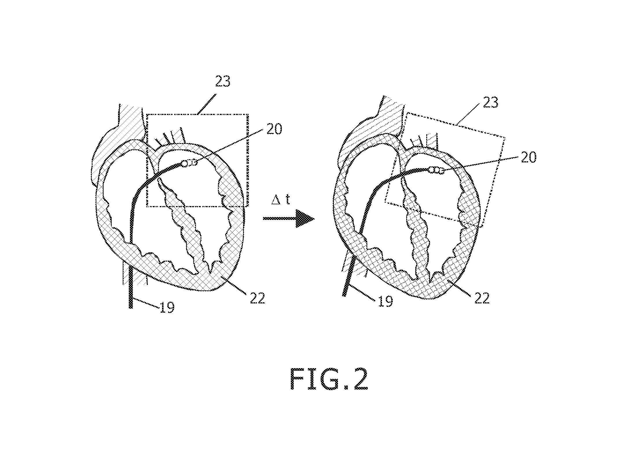
[0021]The method of the invention thus advantageously enables the automatic detection of improperly fixed positioning of a therapeutic or diagnostic interventional device with respect to the anatomy to be treated and / or examined, thereby improving the accuracy of the treatment and, consequently, the result of the treatment. For these reasons, the method of the invention is particularly advantageous for interventional cardiac MR imaging, wherein trackable catheter-like devices are used. An experienced interventionalist is able to firmly fix the interventional instrument with respect to the local cardiac anatomy to either apply a therapy or to perform a certain diagnosis. The tracked interventional instrument than immediately can be used to detect the local motion of the cardiac anatomy very accurately and with high temporal resolution. According to the invention, this tracking data allows to perform an intra-image prospective motion correction, i.e. per acquisition of individual k-space lines or segments, and therefore enables the acquisition of motion compensated MR signals without the need for navigating, ECG triggering or other motion estimation and / or compensation techniques. In this way, faster MR imaging of local anatomy is allowed for, which can be used for increasing the SNR with concurrently reduced motion artifacts. In case of an actively tracked ablation catheter, lesion scanning can be performed effectively without any geometry planning, since the interventional instrument is located right at the lesion and thus can be used directly to define the FOV. This can be extremely useful for creation of repeated point-like ablations, e.g. for the purpose of creating a connected ablation ring or line, as required for pulmonary vein isolation. At the same time, the accuracy of the treatment is significantly improved since unintentional ‘slips’ of the instrument relative to the anatomy to be treated are immediately and reliably recognized due to the principle of the invention.
[0022]The method of the invention can advantageously be combined with PROPELLER imaging. In the known PROPELLER concept (periodically rotated overlapping parallel lines with enhanced reconstruction), the MR signals are acquired in k-space in N strips, each consisting of L parallel lines, corresponding to the L lowest frequency phase encoding lines in a cartesian k-space sampling scheme. Each strip, which is also referred to as k-space blade, is rotated in k-space by an angle 180° / N, so that the total MR data set spans approximately a circle in k-space. One essential characteristic of PROPELLER is that a central circular portion in k-space, having a diameter L is acquired for each k-space blade. This central portion can be used to reconstruct a low-resolution image for each k-space blade. These low-resolution images, or their k-space representations, can be compared to each other to remove in-plane displacements and phase errors, which are due to motion of the examined object. In addition, a suitable technique such as cross-correlation can be employed to determine which k-space blades were acquired with significant through-plane displacement. As the MR signals are combined in k-space before the reconstruction of the final MR image, MR data from k-space blades with the least amount of through-plane motion are preferentially used in regions in which the k-space blades overlap, so that artifacts arising from through-plane motion are reduced. The PROPELLER approach makes use of oversampling in the central portion of k-space in order to obtain an MR image acquisition technique that is robust with respect to motion of the examined body portion. The method of the invention can be used to adjust the position and / or angulation of the individual k-space blades of the PROPELLER sequence on the basis of the collected tracking data. An extremely accurate motion correction is achieved in this way by combination of correlation of the redundant center of k-space data with the collected tracking data from the interventional instrument which is fixed relative to the examined anatomy.

Problems solved by technology

However, cardiac MR imaging is associated with a compromise between spatial resolution, scan time and signal-to-noise ratio (SNR).
Acquisition of sufficient MR data for reconstruction of an image takes a finite period of time.
Motion of the object to be imaged, like the beating motion of the heart in combination with the respiratory motion of the patient, during that finite acquisition time typically results in motion artifacts in the respective reconstructed MR image.
In dynamic MR imaging scans, as required for therapy monitoring, the motion of the examined object during data acquisition leads to different kinds of blurring, mispositioning and deformation artifacts.
The known approaches of motion compensation disadvantageously require an increased scan time due to the decreased scan duty cycle.
Moreover, the above-mentioned navigator technique requires complex scan planning.
However, presently limitations exist with respect to image quality due to limited SNR and motion artifacts.

Method used


Image

  • Interventional MR imaging with motion compensation
  • Interventional MR imaging with motion compensation
  • Interventional MR imaging with motion compensation

Examples


Embodiment Construction

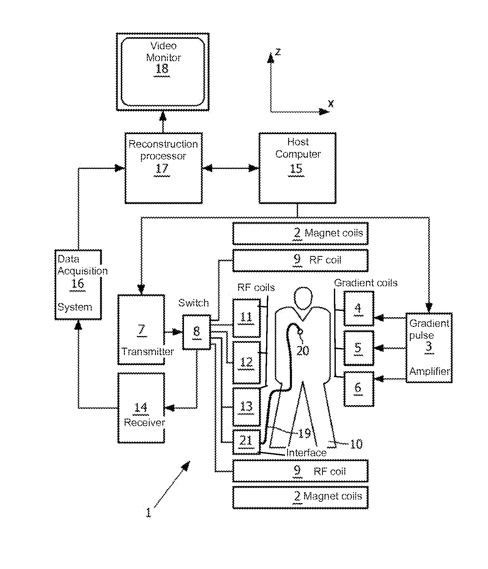
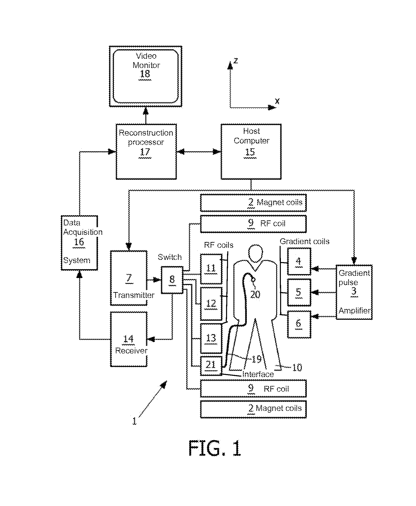
[0028]With reference to FIG. 1, a MR device 1 is shown. The device comprises superconducting or resistive main magnet coils 2 such that a substantially uniform, temporally constant main magnetic field is created along a z-axis through an examination volume.

[0029]A magnetic resonance generation and manipulation system applies a series of RF pulses and switched magnetic field gradients to invert or excite nuclear magnetic spins, induce magnetic resonance, refocus magnetic resonance, manipulate magnetic resonance, spatially and otherwise encode the magnetic resonance, saturate spins, and the like to perform MR imaging.

[0030]More specifically, a gradient pulse amplifier 3 applies current pulses to selected ones of whole-body gradient coils 4, 5 and 6 along x, y and z-axes of the examination volume. A digital RF transmitter 7 transmits RF pulses or pulse packets, via a send- / receive switch 8, to a whole-body volume RF coil 9 to transmit RF pulses into the examination volume. A typical MR...


PUM


Abstract

A method of magnetic resolution (MR) imaging of a moving portion of a body of a patient placed in an examination volume of a MR device. For the purpose of enabling improved interventional MR imaging from acquiring a MR signal data with motion compensation, the invention proposes that the method includes repeated acts of collecting tracking data from an interventional instrument introduced into the portion of the body, subjecting the portion of the body to an imaging sequence for acquiring one or more MR signals therefrom, wherein parameters of the imaging sequence are adjusted on the basis of the tracking data, and reconstructing one or more MR images from the MR signal data set.

Description

FIELD OF THE INVENTION[0001]The invention relates to the field of magnetic resonance (MR) imaging. It concerns a method of MR imaging of at least a moving portion of a body of a patient placed in an examination volume of an MR device. The invention also relates to an MR device and to a computer program to be run on an MR device.BACKGROUND OF THE INVENTION[0002]Image-forming MR methods which utilize the interaction between magnetic fields and nuclear spins in order to form two-dimensional or three-dimensional images are widely used nowadays, notably in the field of medical diagnostics, because for the imaging of soft tissue they are superior to other imaging methods in many respects, do not require ionizing radiation and are usually not invasive.[0003]According to the MR method in general, the body of the patient to be examined is arranged in a strong, uniform magnetic field whose direction at the same time defines an axis (normally the z-axis) of the co-ordinate system on which the ...

Claims


Application Information

Patent Timeline
Patent Type & Authority Patents(United States)
IPC IPC(8): A61B5/055A61B5/06A61B5/00G01R33/567G01R33/28G01R33/48G01R33/565
CPCA61B5/064A61B5/7207G01R33/287G01R33/5673A61B5/055G01R33/4824G01R33/56509A61B2034/2051
Inventor KRUEGER, SASCHA S.WEISS, STEFFENDAVID, BERNDLIPS, OLIVERMANZKE, ROBERT
Owner KONINKLIJKE PHILIPS ELECTRONICS NV
Why Eureka
Try Eureka