Toner production method

a production method and technology of toner, applied in the field of toner production methods, can solve the problems of increased susceptibility to crystallinity loss, inability to form a completely ordered structure, and difficulty in simultaneously realizing the low-temperature fixability and heat-resistant storage of toners, and achieves superior low-temperature fixability and heat-resistant storage. , the effect of easy to obtain

Active Publication Date: 2016-08-30
CANON KK
View PDF14 Cites 38 Cited by
  • Summary
  • Abstract
  • Description
  • Claims
  • Application Information

AI Technical Summary

Benefits of technology

[0016]Namely, the present invention provides a production method that enables a toner to be easily obtained that has superior heat-resistant storability despite having superior low-temperature fixability, and is able to stably sustain that performance even when stored for a long period of time.
[0020]According to the present invention, a production method can be provided that enables a toner to be easily obtained that has superior heat-resistant storability despite having superior low-temperature fixability, and is able to stably sustain that performance even when stored for a long period of time.

Problems solved by technology

However, since lowering Tg leads to a loss of toner heat-resistant storability, it is considered to be difficult for this technique to simultaneously realize both toner low-temperature fixability and heat-resistant storability.
However, since crystalline resins are composed of polymeric substances having a certain degree of molecular weight distribution in the same manner as typical resin materials, they are not always able to form a completely ordered structure.
Moreover, in the case of using such resins as toner materials, since steps are required in an ordinary toner production process in which thermal hysteresis is applied at a temperature equal to or higher than the melting point or the toner is dissolved in an organic solvent together with other materials, crystalline resins become compatible with amorphous resins resulting in increased susceptibility to the loss of crystallinity.
Thus, it is not easy to allow a crystalline resin to be present in a toner while retaining the crystallinity thereof, and normally easily adopts a form consisting of a mixture of portions of high crystallinity and portions of low crystallinity.
As a result, there are many cases in which crystalline resins do not demonstrate their inherent “sharp melt property” even if added to toner, while also demonstrating a decrease in heat-resistant storability.
In addition, toners containing components of low crystallinity and low molecular weight components formed as a result of compatibility end up undergoing further decreases in crystallinity due to the effects of these components in the case of allowing to stand for long periods of time.
However, in the case of holding at a temperature higher than the melting point, energy ends up being applied that is equal to or greater than the intermolecular force required to maintain crystalline structure, and the crystalline structure ends up collapsing.
However, in addition to crystallization requiring a long period of time, due to the large difference between the melting point and storage temperature of the crystalline polyester, the effect thereof is not necessarily adequate.
However, the object of this method is to raise the Tg of the amorphous polyester, and was insufficient for obtaining crystalline polyester having a sharp melt property.
In this method, although heat-resistant storability and low-temperature fixability of the toner can be improved, in addition to requiring heating for a long period of time, the number of steps increases and the procedure is complex.
However, the use of a crystallization technique requiring melting was difficult to apply to granules in the manner of toner in terms of maintaining the particle state of the toner.
As has been described above, production methods for adequately demonstrating the inherent performance of crystalline resin and sustaining stable low-temperature fixability and heat-resistant storability of toner over a long period of time continue to have problems.

Method used


Image

  • Toner production method
  • Toner production method
  • Toner production method

Examples


example 1

[0390]Pressurized annealing was subsequently carried out in Untreated Toner Particle Production Method 1 with the untreated toner particles and carbon dioxide remaining in the granulation tank Ta2 of the device shown in FIG. 3.

[0391]The internal temperature of the granulation tank Ta2 was adjusted to a temperature of 35° C., and the valve V3 was opened to introduce carbon dioxide (purity: 99.99%) into the granulation tank Ta2 from the tank B2 using the pump P2 while stirring at 150 rpm, followed by raising the pressure to 10.0 MPa. When the pressure reached 10 MPa, the pump P2 was stopped and the valve V3 was closed followed by holding at that pressure for 30 minutes. After 30 minutes had elapsed, the pressure regulating valve V5 was opened and carbon dioxide was discharged outside the granulation tank Ta2 followed by reducing the pressure of the tank Ta2 to atmospheric pressure. After discontinuing stirring, the granulation tank Ta2 was opened to obtain “Treated Toner Particles 1” ...

examples 2 to 23

[0394]Toners 2 to 23 subjected to pressurized annealing treatment were obtained in the same manner as Example 1 with the exception of changing the untreated toner particles, retention pressure, retention temperature and retention time in Example 1 to the conditions shown in Table 6.

[0395]However, in the case the pressure of the granulation tank Ta2 prior to pressurized annealing treatment was higher than the retention pressure of pressurized annealing treatment, the pressure regulating valve V5 was opened and retention pressure was adjusted to the prescribed retention pressure by discharging carbon dioxide outside the granulation tank Ta2.

example 24

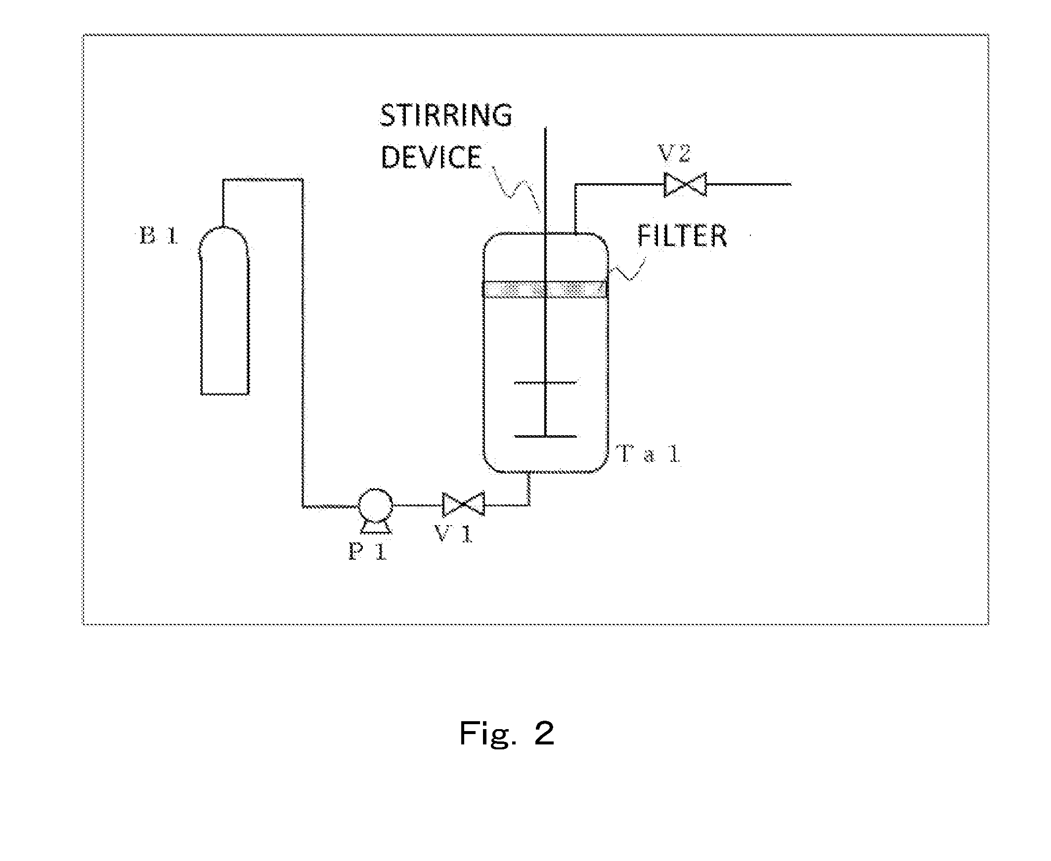
[0396]The valves V1 and V2 in the device shown in FIG. 2 were closed, the Toner Particles 10 were placed in the Tank Ta1 adjusted to an internal temperature of 35° C., and the tank Ta1 was sealed. The valve V1 was opened to introduce carbon dioxide (purity: 99.99%) into the tank Ta1 from the tank B1 using the pump P1 while stirring at 150 rpm, followed by raising the pressure to 10.0 MPa. When the pressure reached 10 MPa, the pump P1 was stopped and the valve V1 was closed followed by holding at that pressure for 30 minutes. After 30 minutes had elapsed, the valve V2 was opened and carbon dioxide was discharged outside the tank Ta1 followed by reducing the pressure of the tank Ta1 to atmospheric pressure. After discontinuing stirring, the tank Ta1 was opened to obtain “Treated Toner Particles 10” that had undergone pressurized annealing treatment.

[0397]1.8 mass parts of hydrophobic silica fine powder treated with hexamethyldisilazane (number-average primary particle diameter: 7 nm) ...


PUM


Abstract

A method for producing a toner that comprises toner particles, each of which comprises a binder resin, which comprises a resin (A) capable of forming a crystalline structure, and a colorant, the method including: a pressure holding step of, after preparing toner particles, holding the toner particles for 5 minutes or more at a pressure of 2.0 MPa or more under conditions of a temperature T1 (° C.) represented by formula (1):20≦T1≦Tp2  (1)(wherein, Tp2 represents the onset temperature of the maximum endothermic peak derived from the resin (A)), wherein a peak temperature Tp1 of the maximum endothermic peak derived from the resin (A) during the first temperature rise of the toner particles as determined by differential scanning calorimetric measurement is 50° C. to 90° C.

Description

BACKGROUND OF THE INVENTION[0001]1. Field of the Invention[0002]The present invention relates to a method for producing a toner used in recording methods using electrophotography, electrostatic recording and toner jet recording.[0003]2. Description of the Related Art[0004]Energy savings have recently come to be considered as an important issue confronting electrophotographic devices, and significant reductions in the amount of heat required by fixing apparatuses are being examined. Thus, there is a growing demand for toner to be able to be fixed with less energy, or in other words, demonstrate “low-temperature fixability”. One example of a technique for enabling fixation at low temperatures involves lowering the glass transition temperature (Tg) of the binder resin present in the toner. However, since lowering Tg leads to a loss of toner heat-resistant storability, it is considered to be difficult for this technique to simultaneously realize both toner low-temperature fixability and...

Claims


Application Information

Patent Timeline
Patent Type & Authority Patents(United States)
IPC IPC(8): G03G9/08G03G9/087
CPCG03G9/0804G03G9/0806G03G9/081G03G9/08788G03G9/08795G03G9/08797
Inventor KINUMATSU, TETSUYAWATANABE, SHUNTAROAOKI, KENJITANI, ATSUSHINAKAGAWA, YOSHIHIROKAYA, TAKAAKIMORI, TOSHIFUMIKOSAKI, YUSUKEKASUYA, TAKASHIGE
Owner CANON KK
Why Eureka
Try Eureka