
Hierarchical and adaptive multi-carrier digital modulation and demodulation

a multi-carrier, digital modulation technology, applied in multi-frequency code systems, sustainable buildings, high-level techniques, etc., can solve the problems of inability to predict standardized mechanisms, insufficient robustness of digital subscriber lines (dsls) to resist transient noise, and inability to accurately estimate the effect of the number of users

Active Publication Date: 2016-09-06
RPX CORP
View PDF9 Cites 0 Cited by
  • Summary
  • Abstract
  • Description
  • Claims
  • Application Information

AI Technical Summary

Benefits of technology

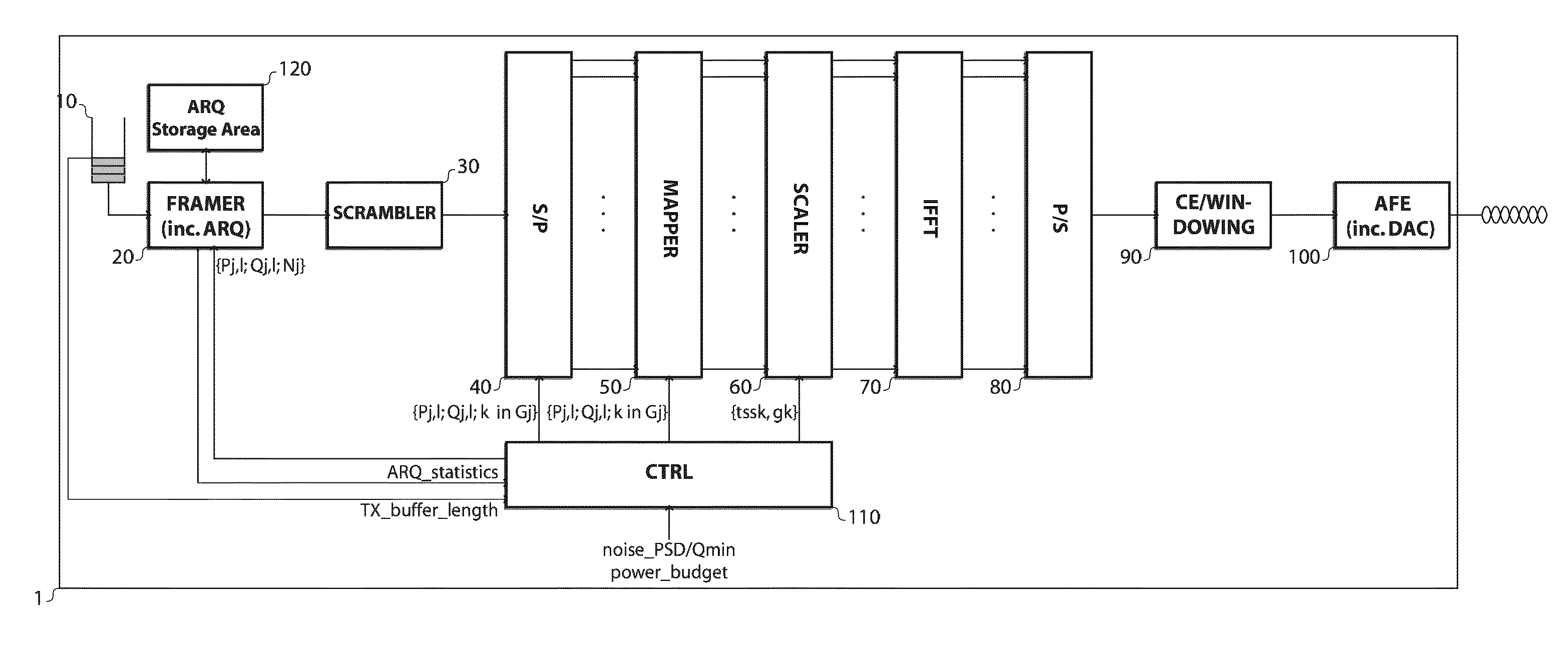
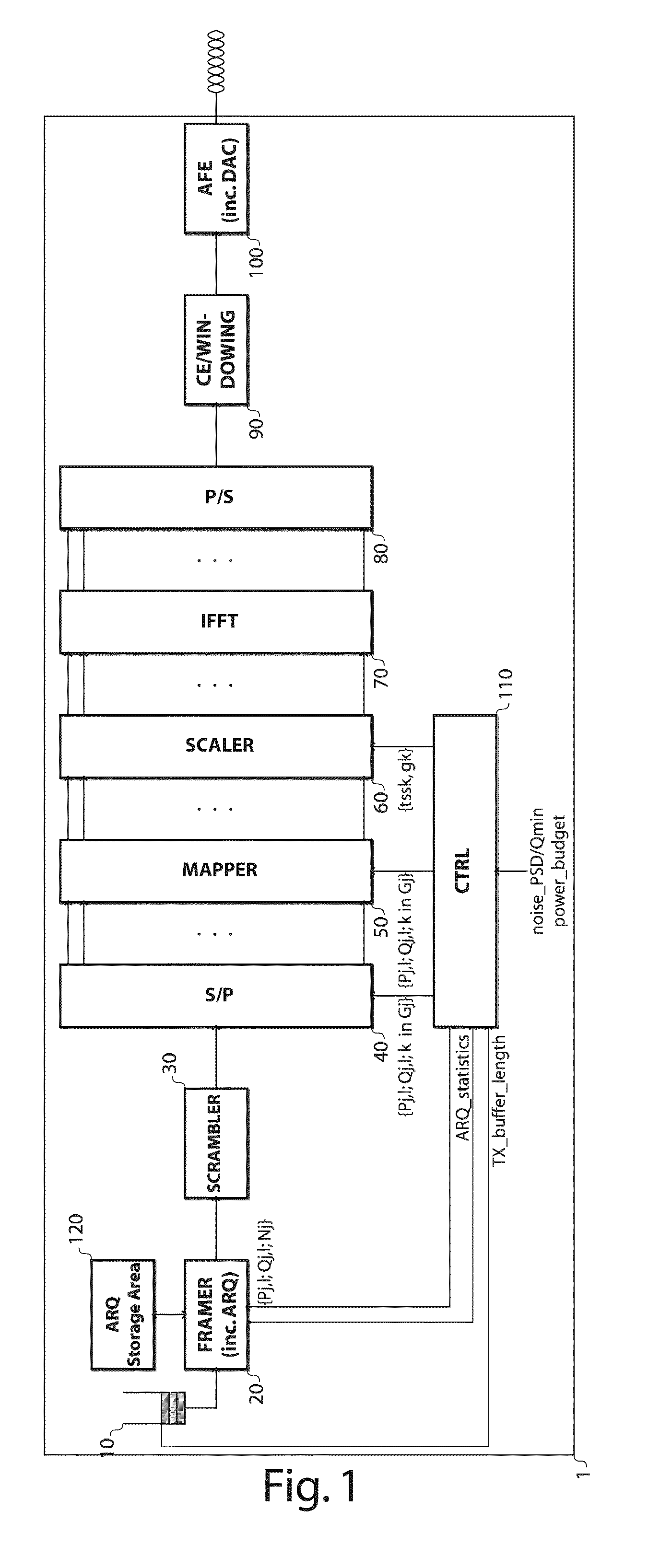
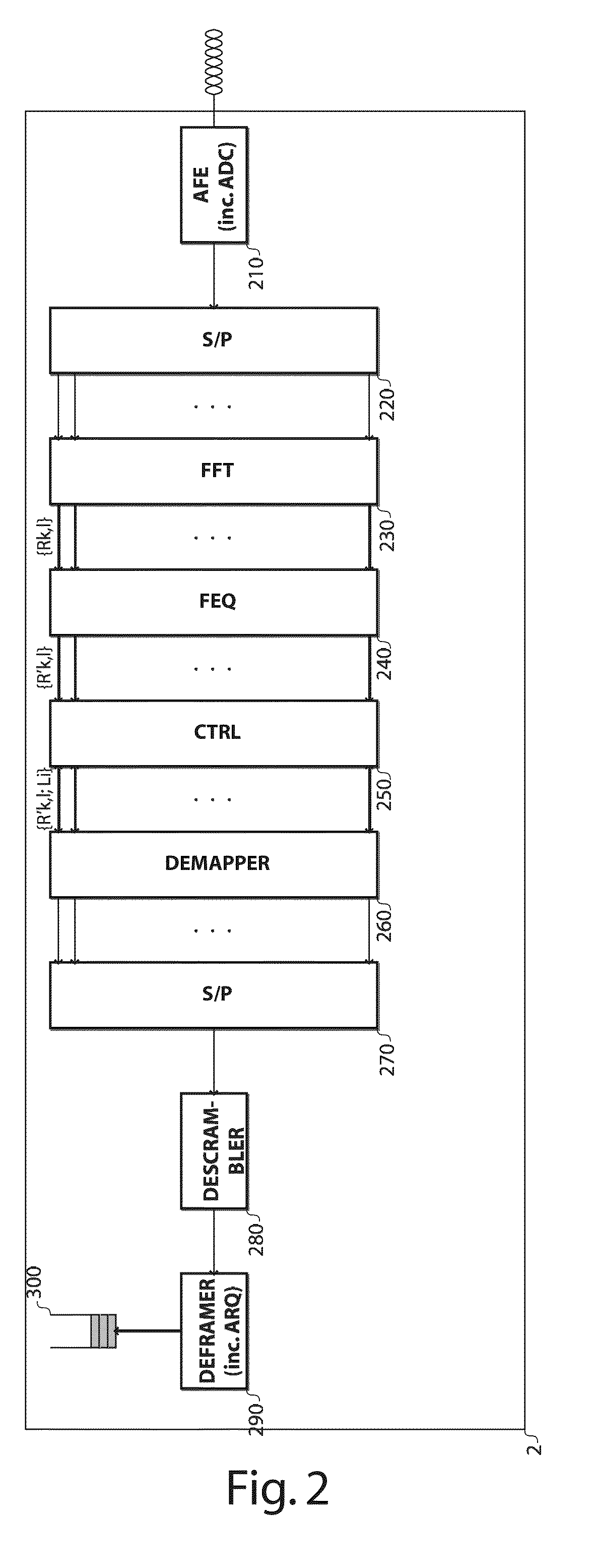
This patent describes a technology that allows a transmitter to automatically adjust the parameters P and Q based on various criteria. This helps the transmitter consume as little transmit power as possible, stay away from noise, and make communication as resilient as possible. The transmitter can also adjust these parameters based on acknowledgement information received from the peer receiver. Additionally, the patent describes a common constellation diagram that allows for blind decoding at the receive side by statistically characterizing the received frequency-samples. This technology does not require using margin or virtual or artificial noise to guarantee quality of service and stability. It can also adapt its transmit power in function of the actual traffic demand, saving more power and controlling power surge. This reduces network management costs and operational expenditures.

Problems solved by technology

However, as the access network remains the bottleneck in the end-to-end connection and due to the continuing demand for ever higher data rates, copper is being replaced by fiber step-by-step.
The cost per user of fiber deployment increases substantially when moving closer to the subscriber premises.
However, Digital Subscriber Line (DSL) is not so robust against transient noise: DSL communications assume a quasi-stable channel and noise environment, and no standardized mechanism is foreseen to cope with fast channel variations.
Hence, operators may require even larger noise margins to cope with this increase in noise dynamics, thereby reducing the projected vectoring gain.
Also here, we can expect an increase in noise dynamics.
In short, current DSL systems are not able to provide end-users with optimal data rates at a right Quality of Service (QoS), and with optimal power per bit.

Method used


Image

  • Hierarchical and adaptive multi-carrier digital modulation and demodulation
  • Hierarchical and adaptive multi-carrier digital modulation and demodulation
  • Hierarchical and adaptive multi-carrier digital modulation and demodulation

Examples


Embodiment Construction

[0067]The following terminology will be consistently used throughout the description:[0068]I denotes the maximum number of hierarchical modulation layers, or alternatively the maximum number of constellation vectors, that can potentially be used by the transmitter and the receiver;[0069]i denotes a modulation layer index, or alternatively a constellation vector index, ranging from 0 to I−1;[0070]Li denotes a particular modulation layer characterized by a particular predefined transmit power;[0071]J denotes the total number of carrier groups;[0072]j denotes a carrier group index ranging from 0 to J−1;[0073]Gj denotes the carrier group with index j;[0074]Nj denotes the number of carriers within the carrier group Gj;[0075]K denotes the total number of carriers;[0076]k denotes a carrier or frequency index ranging from 1 to K;[0077]l denotes a transmit or receive multi-carrier data symbol index,[0078]Vi,k,l denotes the transmit constellation vector at frequency index k for modulation lay...


PUM


Abstract

In an embodiment the method includes, at a transmit side, grouping carriers into carrier groups, and selecting a group constellation diagram for modulation of the carriers of a given carrier group. The selected group constellation diagram is built as a hierarchical sum of I super-imposed constellations vectors having predefined decreasing powers with the P strongest and the Q weakest constellation vectors being omitted. The carriers of the carrier group are modulated by means of the selected group constellation diagram, and P and / or Q parameters per carrier group and per multi-carrier data symbol are adjusted.

Description

[0001]This application is a national phase under 35 U.S.C. §371 of PCT International Application No. PCT / EP2012 / 069955 which has an International filing date of Oct. 9, 2012, which claims priority to European patent application number EP11306381.2 filed Oct. 25, 2011; the entire contents of each of which are hereby incorporated by reference.TECHNICAL FIELD OF THE INVENTION[0002]The present invention relates to digital modulation and demodulation of multi-carrier signals.TECHNICAL BACKGROUND OF THE INVENTION[0003]After their first introduction in the early 1990s, wireline broadband networks, which includes fiber, coaxial cable and twisted pair, have evolved substantially. Despite the inherent attenuation of copper which limits the capacity, transmission over this medium remains attractive as it is abundantly present throughout the world, due to legacy Plain Old Telephony Service (POTS) deployment. Hence, broadband over copper offers substantial deployment cost savings as compared to ...

Claims


Application Information

Patent Timeline
Patent Type & Authority Patents(United States)
IPC IPC(8): H04L27/26H04L5/00H04L27/34H04L1/00
CPCH04L5/0046H04L1/0003H04L27/3488Y02B60/31Y02D30/50H04L27/34
Inventor VANDERHAEGEN, DIRKVAN BRUYSSEL, DANNYMAES, JOCHENDE SCHEPPER, KOENTIMMERS, MICHAEL
Owner RPX CORP
Learn More