

Load sensing on a bearing
- Summary
- Abstract
- Description
- Claims
- Application Information
AI Technical Summary
Benefits of technology
Problems solved by technology
Method used
Image

Examples
Embodiment Construction
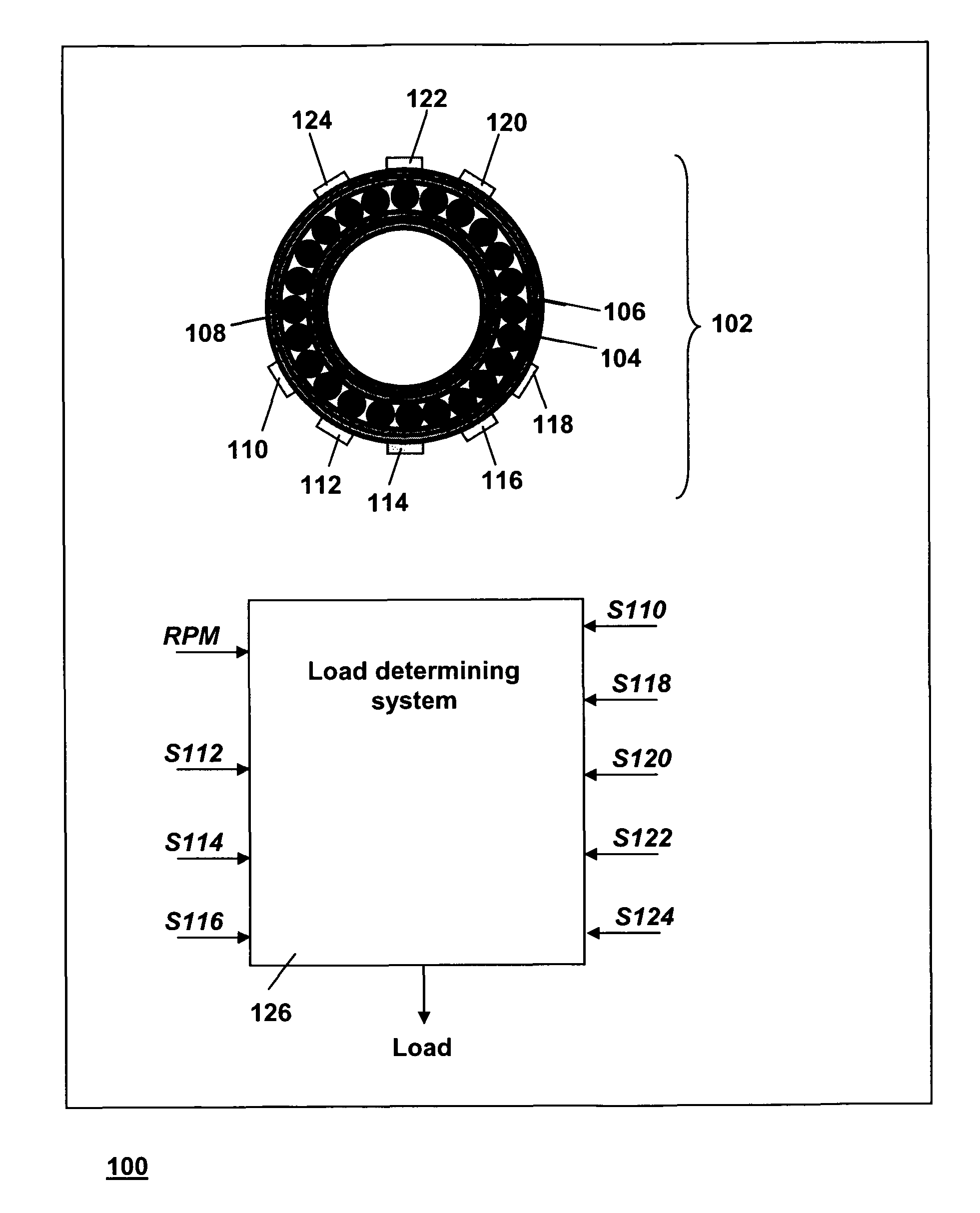
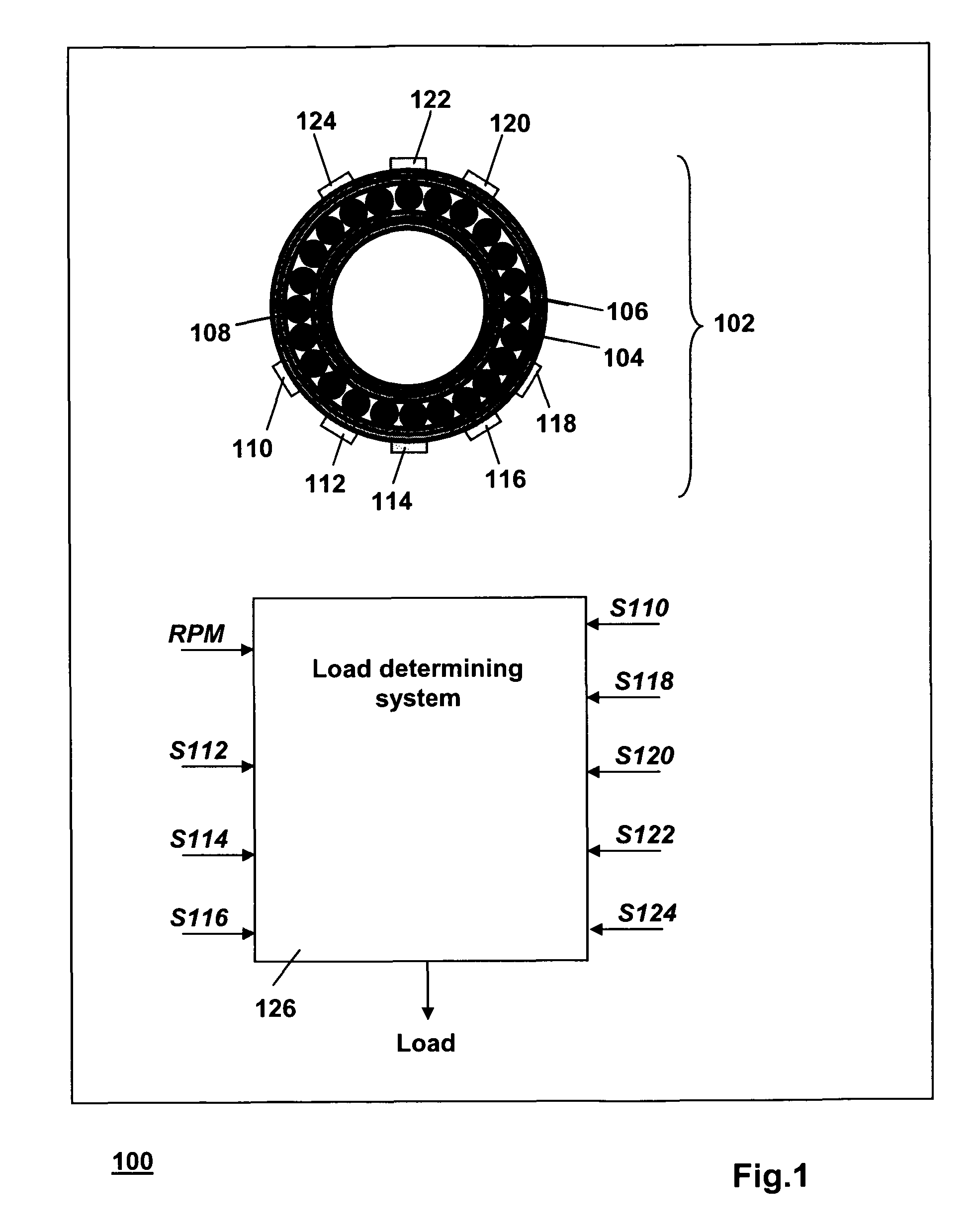
[0045]FIG. 1 is a diagram of a machine 100 that comprises a rolling element bearing 102, a sensor system and a load determining system 126. The bearing 102 is installed as a functional part the machine 100 that is, e.g., a vehicle, a wind turbine, a piece of industrial equipment, an elevator, etc. For example, the rolling element bearing 102 is mounted so as to maintain a position of a shaft relative to a housing, while enabling the shaft to rotate freely around its axis with respect to the housing. In order to not obscure the drawing, the other parts of the machine 100 have not been drawn.
[0046]The rolling element bearing 102 comprises an inner ring 104 and an outer ring 106 that are positioned coaxially. The rolling element bearing 102 further comprises a plurality of rolling elements located between the inner ring 104 and the outer ring 106. In order to not obscure the drawing, only a single one of the plurality of the rolling elements has been indicated with a reference numeral ...
PUM
 Abstract
Description
Claims
Application Information