Device under test tester using redriver

a device under test and tester technology, applied in the direction of individual semiconductor device testing, semiconductor/solid-state device testing/measurement, instruments, etc., can solve the problems of increasing the failure probability of the controller when testing the dut, the limitation of increasing and the limitation of automating the installation or uninstallation of the duts, so as to increase the number of duts tested at one time.

Active Publication Date: 2016-10-04
UNITEST
View PDF9 Cites 3 Cited by
  • Summary
  • Abstract
  • Description
  • Claims
  • Application Information

AI Technical Summary

Benefits of technology

[0026]Accordingly, the present invention has been made keeping in mind the above problems occurring in the prior art, and an object of the present invention is to provide a DUT tester using a redriver, capable of receiving test signals having the same signal integrity from all device under tests (DUTs) by compensating for signal difference according to the variation of the transmission distance through the connection with the redrivers having one-to-one matching relation with DUTs to be tested in order to prevent the signal integrity from being degraded according to the variation of the transmission distance when the test signal passes through a printed circuit board (PCB).
[0027]Another object of the present invention is to provide a DUT tester using a redriver having a dedicated IP address in order to remove signal distortion caused by heat of the chamber in DUT test by reducing cables installed in each PCB corresponding to the number of DUTs to one cable.
[0028]Still another object of the present invention is to provide a DUT tester using a redriver, in which a plurality of PCBs are vertically stacked on each other in a chamber, and DUT test units are installed outside the chamber in such a manner that the DUT test units are one-to-one matched with the PCBs, thereby increasing the number of DUTs to be tested.
[0029]To accomplish these objects, according to one aspect of the present invention, there is provided a device under test (DUT) tester using a redriver. The DUT tester includes a device under test (DUT) test unit, a printed circuit board having a connector for connection with the device under test (DUT) test unit, at least one device under test (DUT) horizontally arranged on the printed circuit board, and redrivers horizontally arranged under the printed circuit board, and connected to the at least one device under test (DUT) in one-to-one matching relation with the at least one device under test (DUT) to compensate for distortion of signal integrity caused according to the variation of the transmission distance of a test signal.
[0036]As described above, in order to compensate for the degradation of the signal integrity according to the variation of the transmission distance, the signal difference according to the variation of the transmission distance can be compensated by employing redrivers for their respective DUTs. Accordingly, the test signals having the same signal integrity are applied to all DUTs, so that the DUTs can be uniformly performed.
[0038]Further, according to the present invention, a plurality of PCBs are vertically installed in the chamber, and DUT test units one-to-one matched with the PCBs are installed outside the chamber, so that the number of DUTs tested at one time can be increased.

Problems solved by technology

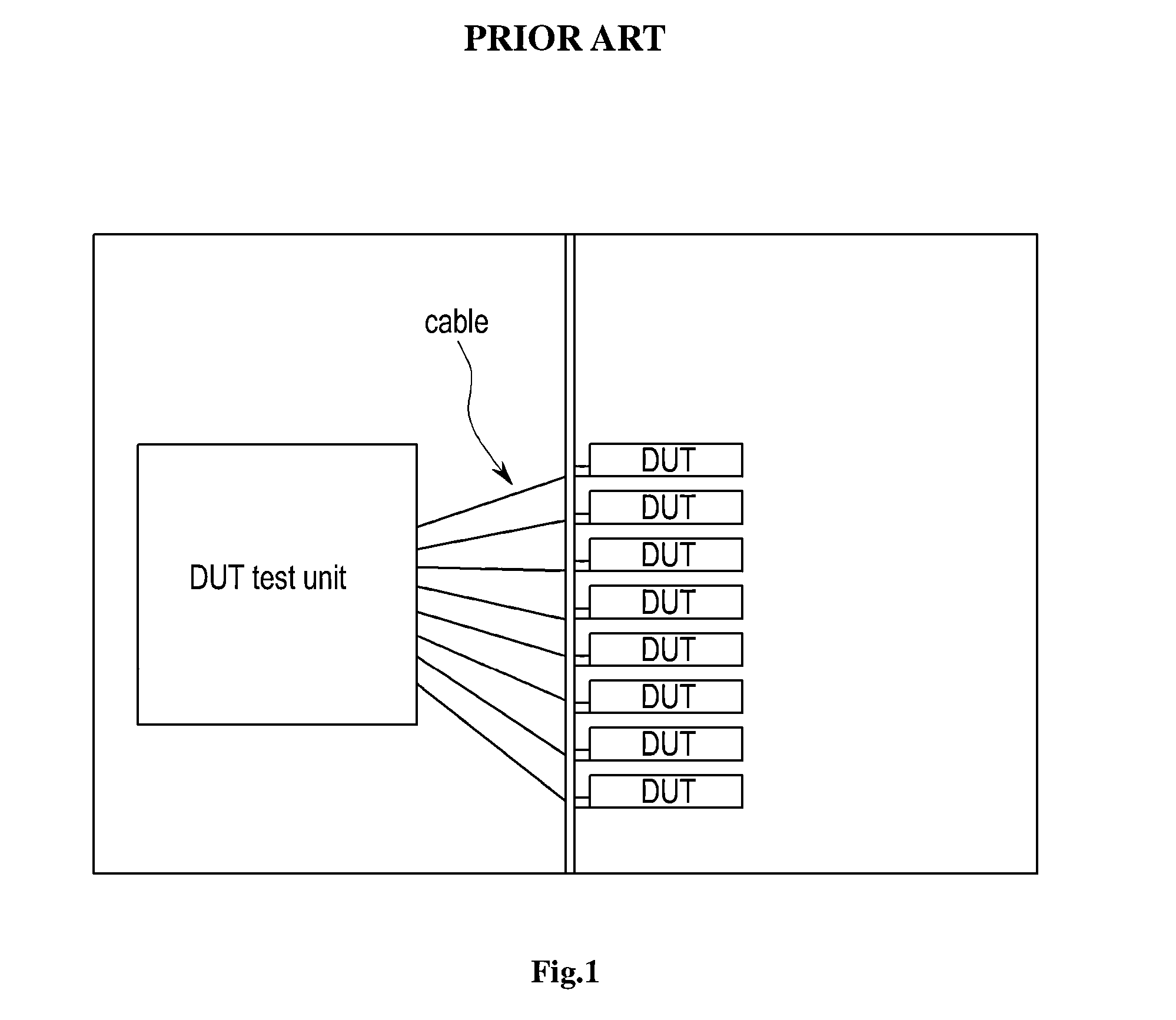
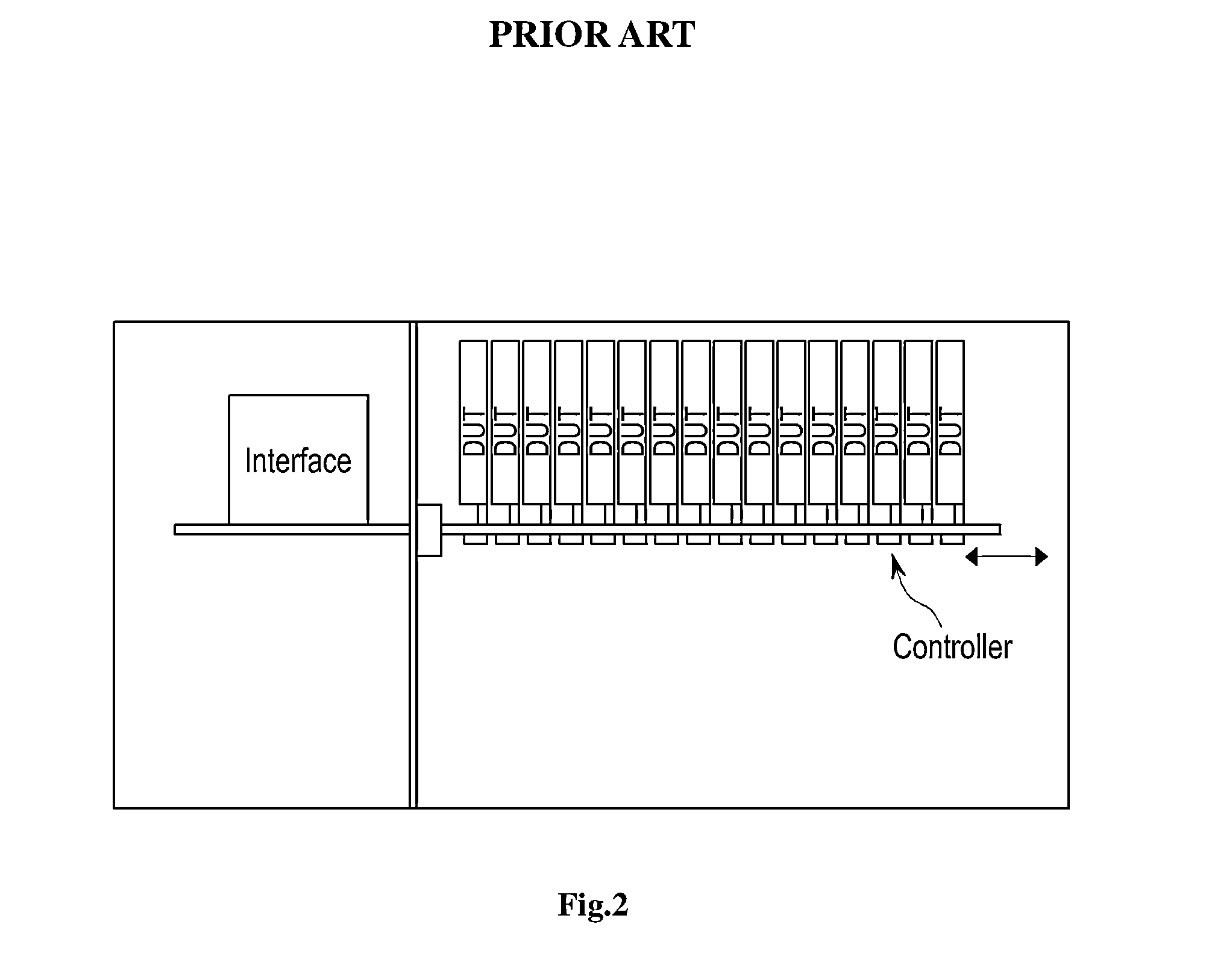
Accordingly, the DUT tester shown in FIG. 1 has a limitation in increasing the number of DUTs since the DUTs are installed on a vertical surface.
In addition, there is a limitation in automating the installation or the uninstallation of the DUTs.
In particular, since the controller or the test unit used in the DUT tester is expensive and represents weak heat resistance, the failure probability of the controller may be increased when testing the DUT.
In addition, fine cables may cause severe degradation to the signal integrity of test signals due to the high-temperature heat in the test chamber.
Accordingly, even if the interface represents the high transfer rate, it is impossible to exactly test DUTs at a test speed suitable for the interface.
Since the degradation of the signal integrity according to the transmission distance is more increased as the transfer rate is increased, the desirable signal integrity may not be obtained corresponding to the transfer rate.

Method used


Image

  • Device under test tester using redriver
  • Device under test tester using redriver
  • Device under test tester using redriver

Examples


Embodiment Construction

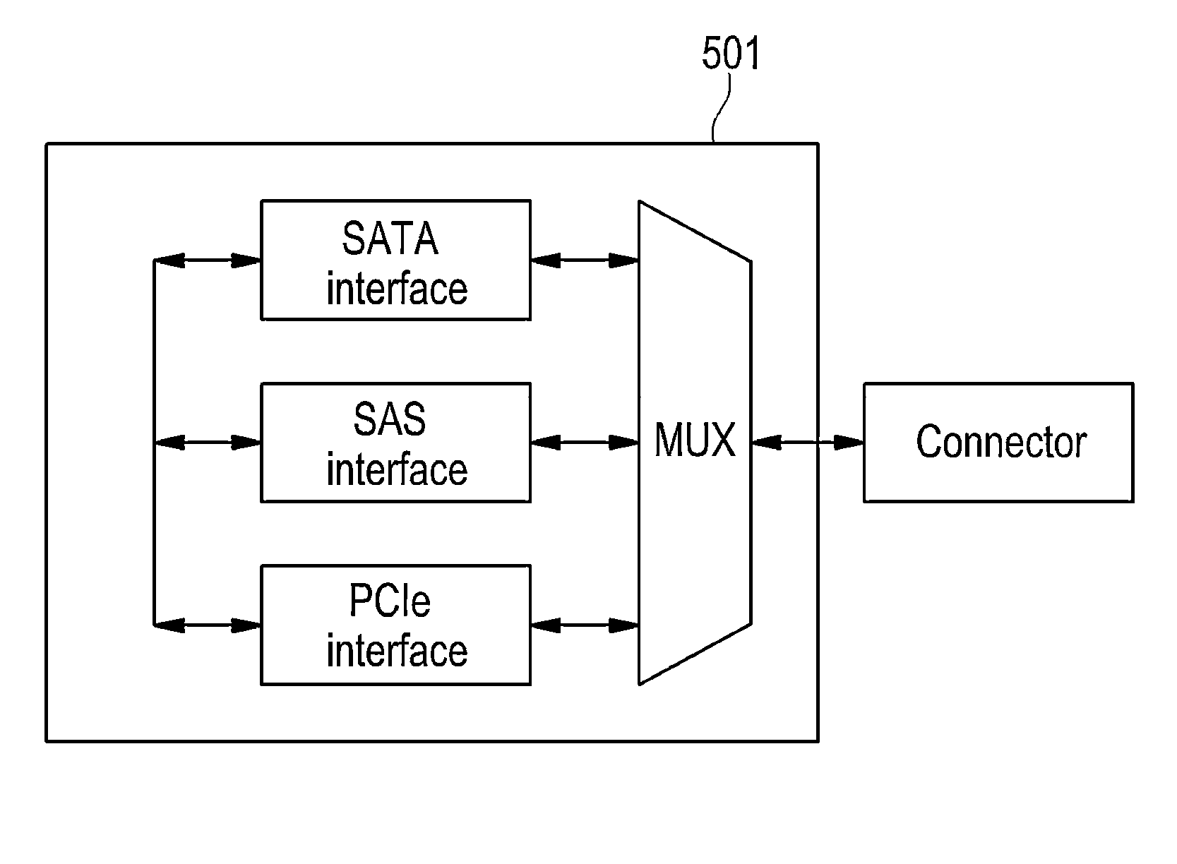
[0048]Although a device under test (DUT) used for the test according to the present invention may include a predetermined type of a semiconductor device such as an SSD, an HDD, or a DRAM, the DUT includes an SSD based on a flash memory device or an SSD based on a DRAM according to an exemplary embodiment of the present invention.

[0049]A solid state drive is a device to store information by using a semiconductor, which is called “semiconductor drive” or “SSD”.

[0050]Since the SSD completely electronically operates, the SSD may significantly reduce long seek time, long response time, long mechanical latency, and a failure rate which are caused in a hard disc drive (HDD) electromechanically operating.

[0051]In particular, most SSDs based on the flash memory represent a read / write speed lower than that of the HDD when data are continuously read or written except for the data access time. However, recently, SSDs having the read / write speed superior to that of the HDD have been introduced.

[...


PUM


Abstract

Disclosed is a device under test (DUT) tester using a redriver. The DUT tester more effectively tests the DUT, which is a predetermined semiconductor device, by applying an electrical signal to the DUT and measuring the electrical signal. The DUT tester includes a DUT test unit, a printed circuit board (PCB) provided therein with connectors for the connection with the DUT test unit, one DUT or more horizontally arranged on the PCB, and redrivers horizontally provided under the PCB and one-to-one matched with one DUT or more to compensate for the distortion of the signal integrity of test signals caused according to the variation of the transmission distance.

Description

BACKGROUND OF THE INVENTION[0001]1. Field of the Invention[0002]The present invention relates to a device under test (DUT) tester using a redriver, capable of more effectively testing the DUT, which is a predetermined semiconductor device, by applying an electrical signal to the DUT and measuring the electrical signal. In more particular, the present invention relates to a device under test (DUT) tester by using a redriver, which includes a DUT test unit, a printed circuit board (PCB) provided therein with connectors for the connection with the DUT test unit, one DUT or more horizontally arranged on the PCB, and redrivers horizontally provided under the PCB and one-to-one matched with one or more DUT to compensate for the distortion of the signal integrity of test signals caused according to the variation of the transmission distance.[0003]2. Description of the Related Art[0004]In order to properly ensure the functionality and the reliability of semiconductor devices, the manufactur...

Claims


Application Information

Patent Timeline
Patent Type & Authority Patents(United States)
IPC IPC(8): G01R31/00G01R31/319G01R31/26H01L21/66
CPCG01R31/003G01R31/31905G01R31/26H01L22/00
Inventor OH, JIN AN
Owner UNITEST
Why Eureka
Try Eureka