
Controlling data center cooling systems

a cooling system and data center technology, applied in process and machine control, lighting and heating equipment, instruments, etc., can solve the problems of increasing the cost of cooling system operation, so as to achieve high scalable, new control algorithms, and avoid performance constraints of conventional building automation systems

Active Publication Date: 2016-10-25
GOOGLE LLC
View PDF15 Cites 29 Cited by
  • Summary
  • Abstract
  • Description
  • Claims
  • Application Information

AI Technical Summary

Benefits of technology

The patent describes a system and method for controlling equipment that cools electronic equipment. The system is designed to be distributed and fail-tolerant, meaning it can handle failures without shutting down. It can also be highly scalable, meaning it can handle large numbers of devices. The system is also modular and extendible, meaning new control algorithms can be easily added. Additionally, the system provides secure communication between controllers and computational software that controls the equipment. Overall, the system offers improved reliability, flexibility, and security for data centers.

Problems solved by technology

Many forget that this speed often comes with a cost—higher power consumption.
Thus, the cost of removing all of the heat can also be a major cost of operating large data centers.
That cost typically involves the use of even more energy, in the form of electricity and natural gas, to operate chillers, condensers, pumps, fans, cooling towers, and other related components.
Heat removal can also be important because, although microprocessors may not be as sensitive to heat as are people, increases in temperature can cause great increases in microprocessor errors and failures.
In sum, a data center requires a large amount of electricity to power the critical load, and even more electricity to cool the load.

Method used


Image

  • Controlling data center cooling systems
  • Controlling data center cooling systems
  • Controlling data center cooling systems

Examples


Embodiment Construction

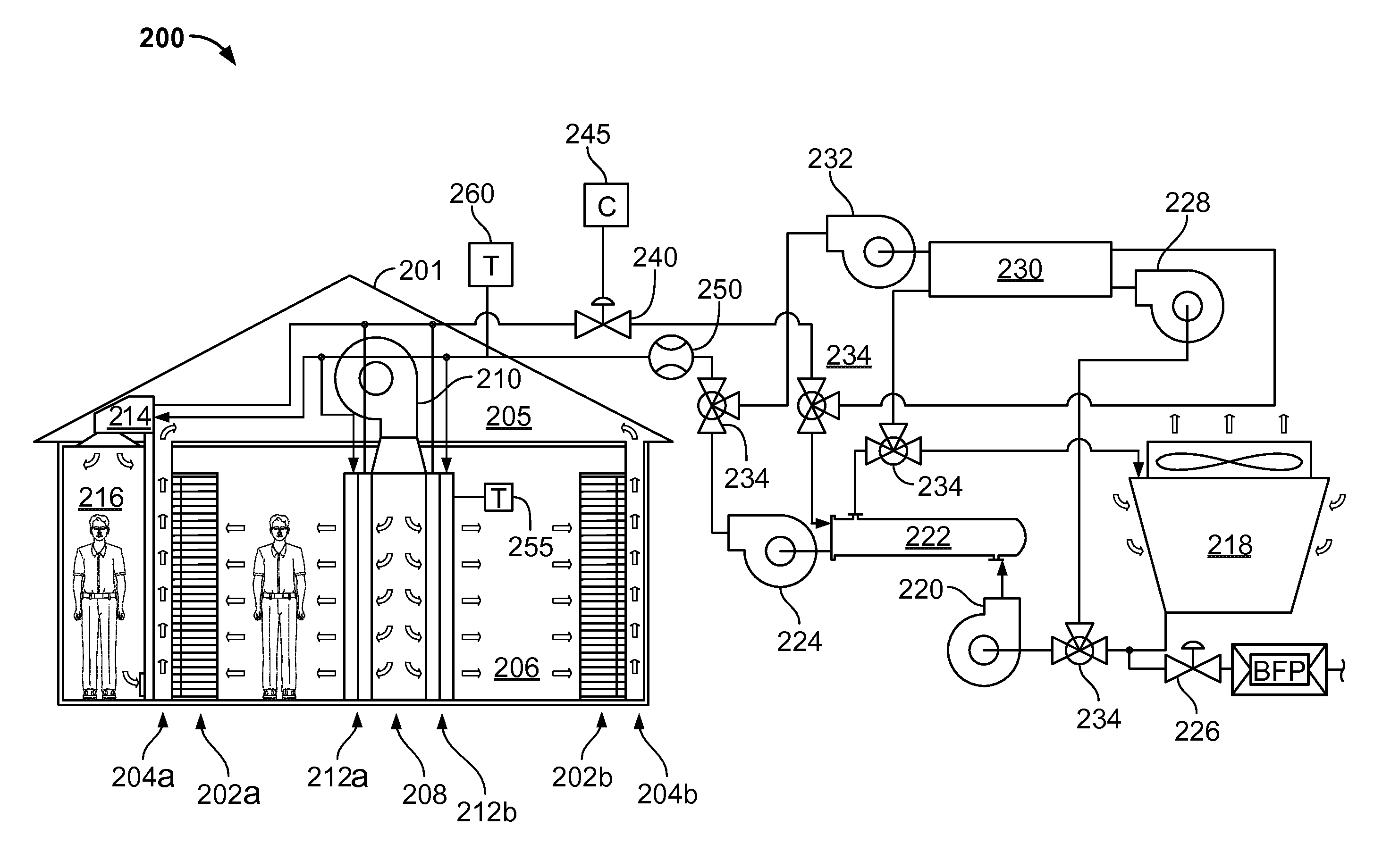
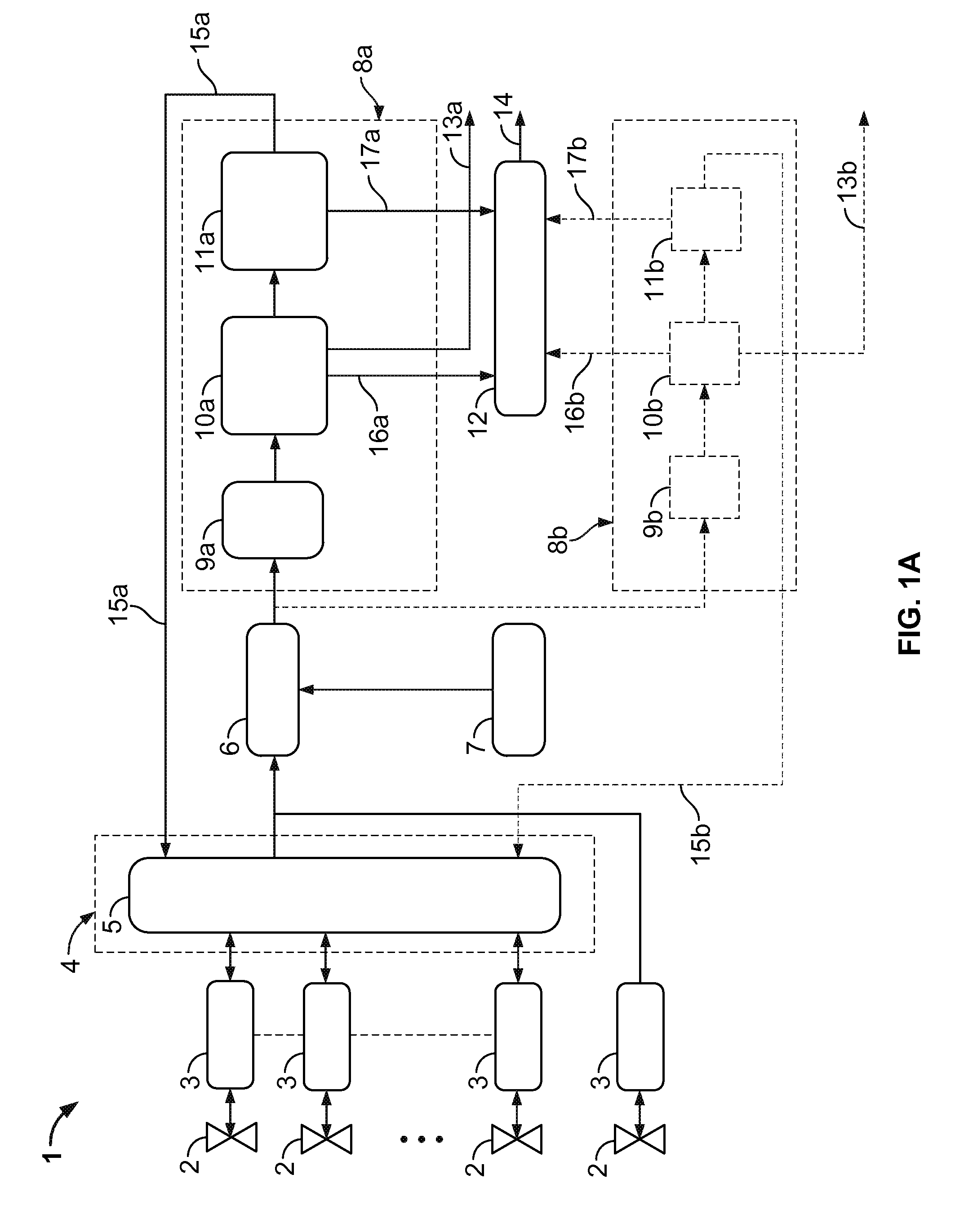
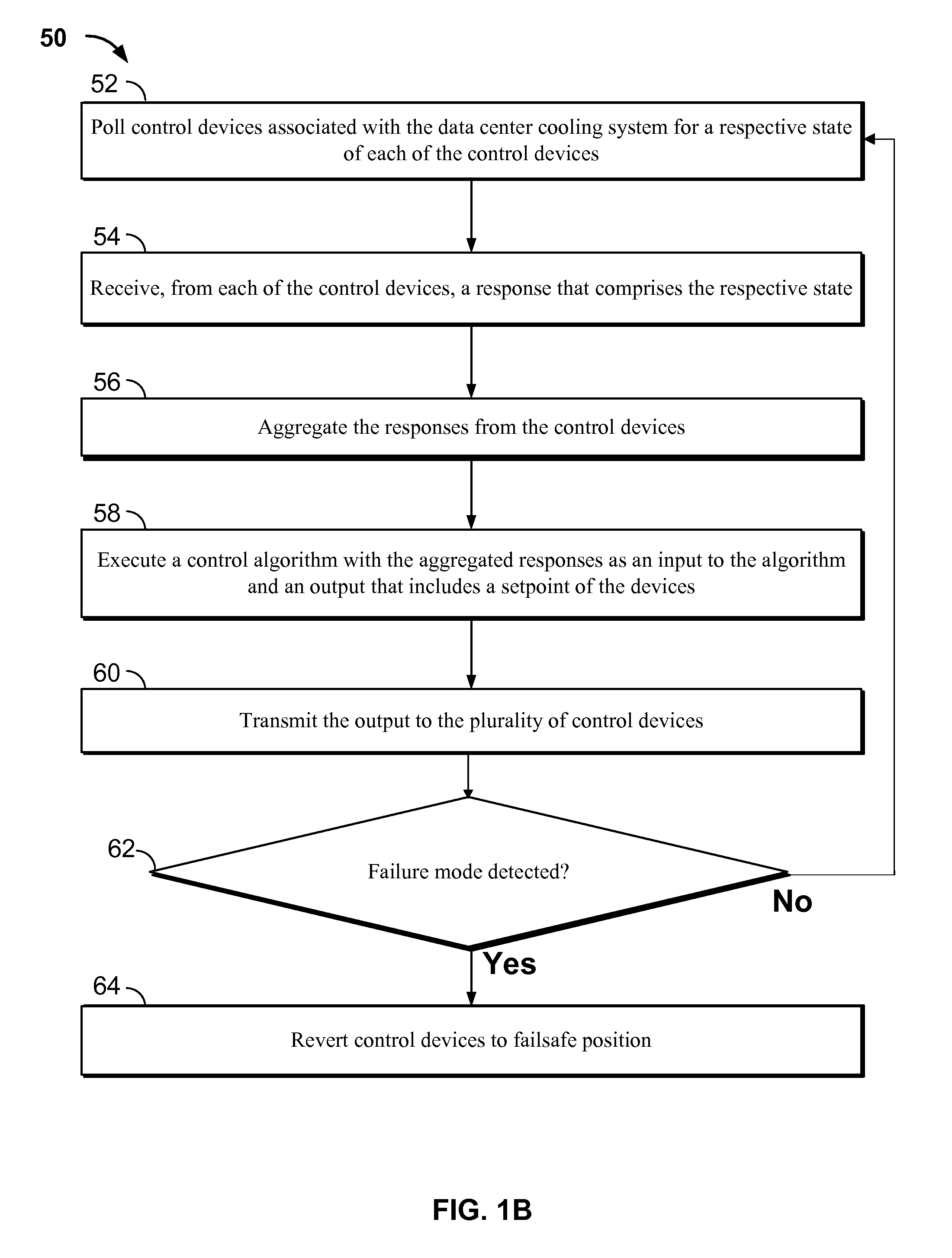
[0029]This disclosure relates to systems and methods for controlling a cooling system or other infrastructure system (e.g., lighting system, building management system, or otherwise) in a data center. In some aspects, the systems and method include a software framework that, for example, can be executed on one or more computing devices, such as, for instance, one or more rack-mounted computing devices in the data center. The software framework polls multiple controllers that are communicably coupled to controlled / actuatable devices (e.g., valves, fans, pumps, lights, doors, and otherwise) for their respective states. The state data may be aggregated and fed into one or more control algorithms to determine a new and / or adjusted setpoint for the devices. The new and / or adjusted setpoint is communicated back to the controlled devices.

[0030]FIG. 1A illustrates an example computer-implemented system 1 for controlling a cooling system for a data center. The system 1, as illustrated, inclu...


PUM


Abstract

Techniques for controlling a data center cooling system include polling a plurality of control devices associated with the data center cooling system for a respective state of each of the control devices; receiving, from each of the plurality of control devices, a response that includes the respective state; aggregating the responses from the plurality of control devices; executing a control algorithm that includes the aggregated responses as an input to the algorithm and an output that includes a setpoint of the plurality of control devices; and transmitting the output to the plurality of control devices.

Description

CROSS REFERENCE TO RELATED APPLICATION[0001]This application claims priority under 35 U.S.C. §119 to U.S. Provisional Patent Application Ser. No. 61 / 778,741, filed Mar. 13, 2013, the entire contents of which is incorporated by reference herein.TECHNICAL BACKGROUND[0002]This disclosure relates to systems and methods for controlling systems and equipment that provide cooling for areas that contain electronic equipment, such as computer server rooms and server racks in computer data centers.BACKGROUND[0003]Computer users often focus on the speed of computer microprocessors (e.g., megahertz and gigahertz). Many forget that this speed often comes with a cost—higher power consumption. For one or two home PCs, this extra power may be negligible when compared to the cost of running the many other electrical appliances in a home. But in data center applications, where thousands of microprocessors may be operated, electrical power requirements can be very important.[0004]Power consumption is ...

Claims


Application Information

Patent Timeline
Patent Type & Authority Patents(United States)
IPC IPC(8): F28F27/02G05D23/19H05K7/20
CPCH05K7/208G05D23/1917F28F27/02H05K7/20836H05K7/2079F28D15/00G05D23/1932F28D2021/0019F28D1/024
Inventor PETTIS, NATHANIEL EDWARDTIBBITS, ANDREW H.
Owner GOOGLE LLC
Learn More