Strain sensor

a sensor and cnt fiber technology, applied in the field of strain sensors, can solve the problems of difficult to obtain decrease in distance between cnt fibers, etc., and achieve the effect of inhibiting unexpected resistance changes, low compression in the thickness direction, and high linearity of resistance chang

Active Publication Date: 2016-10-25
YAMAHA CORP +1
View PDF60 Cites 9 Cited by
  • Summary
  • Abstract
  • Description
  • Claims
  • Application Information

AI Technical Summary

Benefits of technology

[0009]The present invention was achieved in view of the aforementioned circumstances, and has as its object to provide a strain sensor that is capable of inhibiting the occurrence of contamination of the CNT film by foreign substances and enhancing the durability of the sensor function while improving the linearity of the resistance change and responsiveness.
[0011]This strain sensor is capable of sensing strain by the change in electrical resistance of the CNT film upon extending or contracting in the direction of causing the pair of electrodes to respectively move away from or approach each other (electrode arrangement direction). Since the orientation direction of the CNT fiber bundles that the CNT film has and the electrode arrangement direction are approximately the same direction, and the peripheral surface of the CNT fiber bundles that consist of the plurality of CNT fibers is covered with the resin layer in this strain sensor, the linearity of the resistance change of the CNT film is high.
[0013]In contrast, in the strain sensor of the present invention, since resistance changes occur due to the CNT fibers in the CNT bundles breaking and separating at random locations as a result of extension of the strain sensor, and the compression in the thickness direction is low, the linearity of the resistance change is high. The periphery of the CNT fiber bundles of this strain sensor is covered with a resin layer. Also, the resin layer partially impregnates to the periphery of the CNT fiber bungles so as to form an impregnated portion. This resin layer and the impregnated portion play the role of a guide, and since a non-impregnated portion, which is not impregnated with the resin layer, of the CNT fiber bundle is prevented from coming into contact with other fiber bundles due to free movement other than in the extension / contraction direction, it is possible to inhibit unforeseen resistance changes, and further increase the linearity of the resistance change.
[0014]Furthermore, since the periphery of the CNT fiber bundles in the strain sensor of the present invention is covered with the resin layer and the impregnated portion as described above, when the CNT fibers in the CNT fiber bundles are broken, a space that is isolated from the outside is formed between the broken end portions of the CNT fibers. The pressure in this space is considered to be lower than the atmospheric pressure (negative pressure), and so during contraction of the strain sensor (during release of the strain), the contraction of the strain sensor is biased by the contraction force of this gap. Moreover, within this gap, since friction among the CNT fibers and between the CNT fibers and the periphery resin is reduced, movement of the CNT fibers is not easily restricted by the residual stress of the resin. As a result, since the broken end portions of the CNT fibers quickly reestablish contact during contraction of the strain sensor, this strain sensor can obtain a high responsiveness.
[0015]In addition, in the strain sensor of the present invention, the CNT film has the resin layer and the impregnated portion that covers the periphery of the CNT fiber bundles, whereby it is possible to prevent contamination of the CNT film by foreign substances. Since the CNT fiber bundles and the resin layer are connected by the impregnated layer, it is possible to prevent from falling off of the CNT fibers so as to enhance the durability of the sensor function.
[0016]As described above, the strain sensor of the present invention is capable of inhibiting the occurrence of contamination of the CNT film by foreign substances and enhancing the durability of the sensor function while improving the linearity of the resistance change and responsiveness. Accordingly, the strain sensor of the present invention can be widely utilized as a pressure sensor, a load cell, a torque sensor, a position sensor and the like.

Problems solved by technology

In this perpendicular arrangement strain sensor, since extension in the electrode arrangement direction leads to a dramatic increase in the distance between the CNT fibers in the extension direction, and compression applied in the thickness direction of the strain sensor causes a decrease in the distance between the CNT fibers, linearity of the resistance change is difficult to obtain.

Method used


Image

  • Strain sensor
  • Strain sensor
  • Strain sensor

Examples


first embodiment

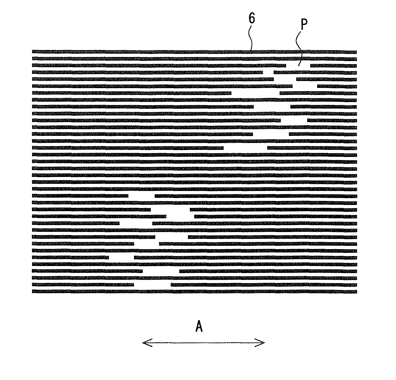
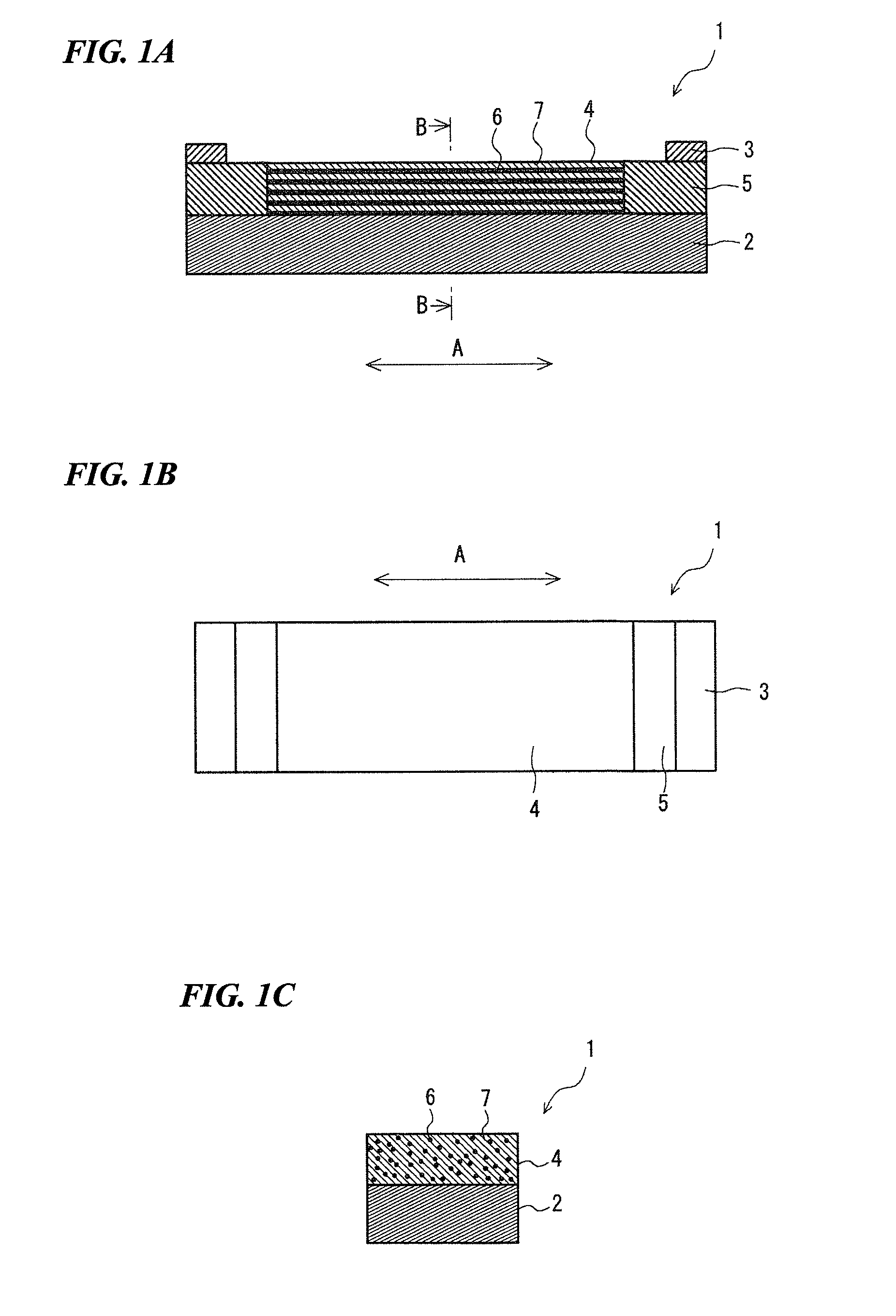
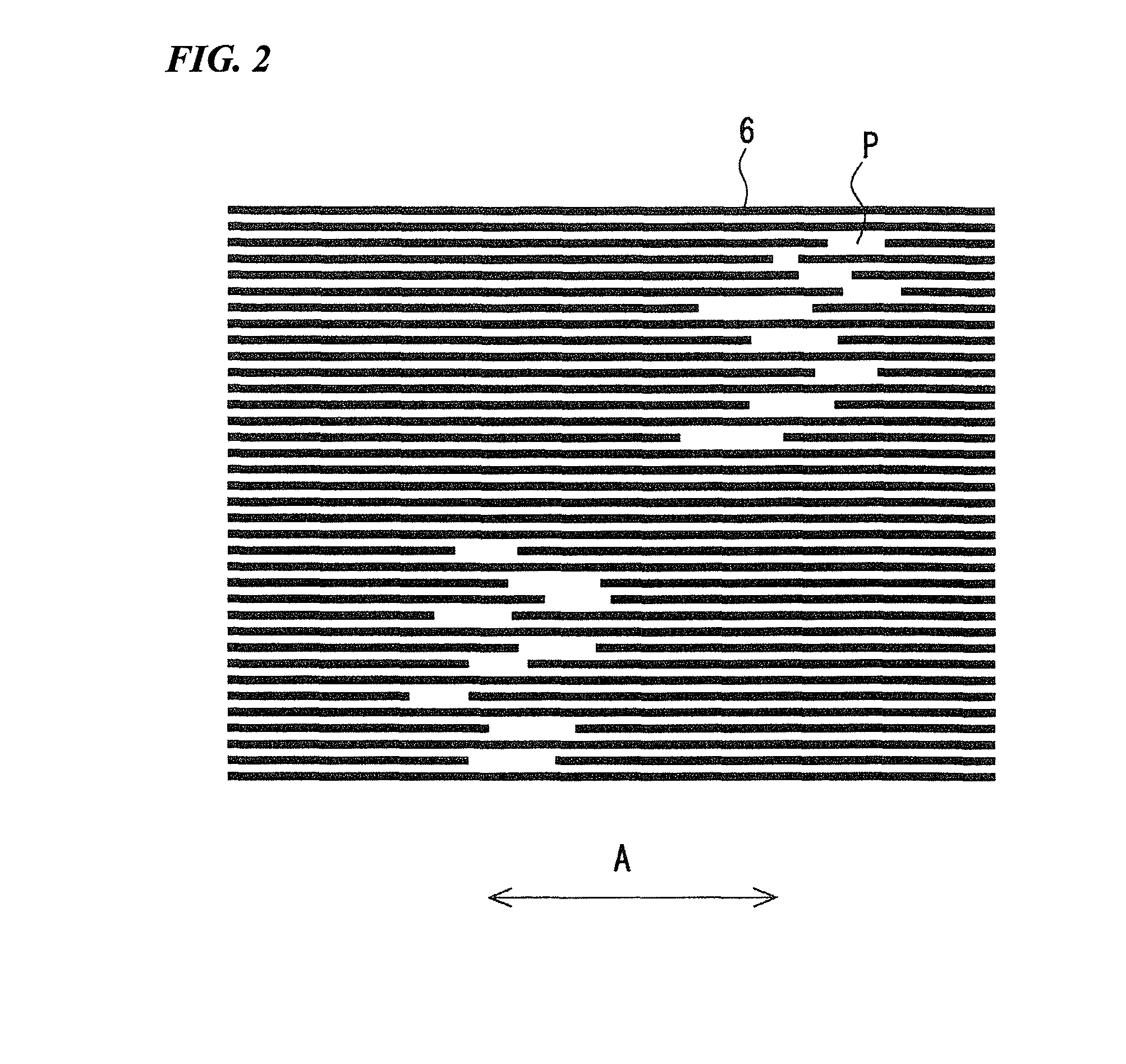
[0029]Referring to FIGS. 1A to 1C, a strain sensor 1 is provided with a substrate 2, a CNT film 4 that is provided on the surface side of this substrate 2 and that has a plurality of CNT fibers oriented in one direction, and a pair of electrodes 3 that are arranged at both ends of the CNT fibers in the orientation direction A.

(Substrate)

[0030]The substrate 2 is a plate-shaped body that has flexibility. The size of the substrate 2 is not particularly limited, and for example the thickness may be between 10 μm and 5 mm, the width between 1 mm and 5 cm, and the length between 1 cm and 20 cm.

[0031]The material of the substrate 2 is not particularly limited provided it has flexibility, with examples including synthetic resin, rubber, a nonwoven fabric, and a metal or metallic compound with a deformable shape or material. The substrate 2 should be an insulator or a material with a high resistance value, but in the case of using a material with a low resistance value such as metal, an insu...

second embodiment

[0085]A strain sensor 11 of FIG. 7 is mainly provided with the substrate 2, the pair of electrodes 3, the CNT film 4, and an assist layer 8 that is laminated on the back surface of the substrate 2. The substrate 2, the electrodes 3 and the CNT film 4 are the same as the strain sensor 1 shown in FIG. 1A to 1C, so they shall be given the same reference numerals, and their explanation shall be omitted.

[0086]The assist layer 8 is a material with a different Young's modulus than the substrate 2. By having this assist layer 8 be a member with a lower Young's modulus than the substrate 2, it is possible to enhance the following performance in the case of directly affixing the strain sensor 11 to skin or the like. Also, by making the assist layer 8 be a member with a higher Young's modulus than the substrate 2, it is possible to control the extension / contraction rate of the strain sensor 11 to prevent a delay in strain detection.

[0087]It is possible to suitably select the material of the as...

third embodiment

[0092]A strain sensor 21 of FIG. 8 is mainly provided with the substrate 2, the pair of electrodes 3, the CNT film 4, and an assist layer 9 that is laminated on the surface of the CNT film 4. The substrate 2, the electrodes 3 and the CNT film 4 are the same as the strain sensor 1 shown in FIGS. 1A to 1C, so they shall be given the same reference numerals, and their explanation shall be omitted. In addition, the assist layer 9 may be the same as the one in the strain sensor 11 of FIG. 11. Note that the assist layer 9 preferably also covers the conductive layer 5 as shown in FIG. 8.

[0093]Similarly to the strain sensor 11 of the second embodiment, it is possible by means of the assist layer 9 laminated on the surface of the CNT film 4 to improve the following performance of the strain sensor 21 with respect to movement of the body on which the strain sensor is affixed and also its detection sensitivity. Also, it is possible to more reliably prevent contamination of the CNT film 4 by fo...


PUM

PropertyMeasurementUnit
lengthsaaaaaaaaaa
lengthsaaaaaaaaaa
thicknessaaaaaaaaaa

Abstract

A strain sensor provided with a substrate that has flexibility; a carbon nanotube (CNT) film that is provided on the surface of the substrate and that has a plurality of CNT fibers oriented in one direction; and a pair of electrodes that are arranged at both ends in the orientation direction of the CNT fibers in the CNT film; in which the CNT film has a plurality of CNT fiber bundles that consist of the plurality of CNT fibers, and a resin layer that covers the peripheral surface of the plurality of the CNT fiber bundles and joins with the surface of the substrate.

Description

BACKGROUND OF THE INVENTION[0001]1. Field of the Invention[0002]The present invention relates to a strain sensor.[0003]Priority is claimed on Japanese Patent Application No. 2013-100751, filed May 10, 2013, and Japanese Patent Application No. 2014-2044, filed Jan. 8, 2014, the content of which are incorporated herein by reference.[0004]2. Description of Related Art[0005]A strain sensor that detects strain is constituted so as to detect strain from the resistance change of a resistive body with respect to strain (extension and contraction). A metal or semiconductor is generally used as this resistive body. However, since the reversible amount of extendable and contractable deformation of a metal or semiconductor is small, the applications of a strain sensor are limited.[0006]Therefore, a device using carbon nanotubes (CNT) as the resistive body has been proposed (refer to Japanese Unexamined Patent Application Publication No. 2003-227808). In this device, a CNT film or the like is us...

Claims


Application Information

Patent Timeline
Patent Type & Authority Patents(United States)
IPC IPC(8): G01L1/22B82Y30/00
CPCG01L1/2287B82Y30/00Y10T156/1092G01L1/20
Inventor SUZUKI, KATSUNORISAKAKIBARA, SHINGOYATAKA, KOJIOKUMIYA, YASUROSUGIURA, MASAHIROINOUE, YOKU
Owner YAMAHA CORP
Why Eureka
Try Eureka