
System and method for assessing retinal functionality

a retinal function and functional assessment technology, applied in the field of retinal functional assessment systems and methods, can solve the problems of not entirely satisfactory, declining commercial availability of crts, and alternatively not entirely suitable for use in optical stimulators, and achieve the effect of reducing the deficiencies of such known optical stimulators

Inactive Publication Date: 2016-11-01
ANNIDIS
View PDF4 Cites 7 Cited by
  • Summary
  • Abstract
  • Description
  • Claims
  • Application Information

AI Technical Summary

Benefits of technology

The present invention aims to improve optical stimulators by separating the generation of the image from the illumination. This is achieved by using a digital micro-mirror device (DMD) and a controller to configure the micro-mirrors to form a stimulus pattern. The DMD can be controlled to create coded image patterns that can be projected onto the retina or other parts of the visual system for optical stimulation. The system includes optics, a light source, the DMD, and a sensor to measure the response of the eye or other parts of the visual system to light. The technical effects of this invention include improved optical stimulators with improved spatial resolution and greater control over the stimulus pattern, as well as a better understanding of the response of the visual system to light.

Problems solved by technology

Although CRTs have seen widespread use in optical stimulators, they are not entirely satisfactory for a variety of reasons.
Finally, the commercial availability of CRTs has been declining and clinicians, experimenters and instrument makers have been actively seeking suitable alternatives.
However, these alternatives also are not entirely suitable for use in optical stimulators.
During this time a moving band of light leakage from the backlight has been noted in many displays, which can degrade the optical stimulus spatial / temporal format.
Attempts to ameliorate this problem included building custom controllers for the backlights to dim them during the pixel change period, leading to added complexity and expense.
The resulting delay between the time that a frame is sent to the display and the time that frame is displayed can be a significant problem with LCDs because optical stimulators generally require exact timing between application of the stimulus and triggering of the response measurement.
In fact, the standards for latency in some ERG measurements have had to be modified to deal with this effect and this issue has created difficulties in comparing results from the two systems and between measurements made using different LCD displays.
Again, there is no user control of the wavelengths of the illumination; the LCD manufacturer picks the filters to apply to the white backlight to generate the display colors.
These displays generally use as the image source a compact LCD display and have the characteristic limitations of this technology as described above.
Many of the LCD problems also apply to the newer organic liquid crystal (OLED) displays with the exception of the light leakage problem which does not occur since the output of each pixel (LED) is directly controlled.
A disadvantage of such LED arrays, however, is a lack of flexibility in the patterns produced since the LEDs are in fixed locations.
In addition, the LEDS are seen as discrete light sources by the eye, which does not fit with most of the assumptions about the properties of optical stimulators.
A further limitation is that CRT and LCD displays and custom LED arrays are viewed at a distance by the patient and so the environmental and experimental conditions, ambient light, display luminance, distance etc., need to be controlled carefully because the illuminance of the stimuli on the retina depends on all these factors, plus the anterior clarity of the subject's eye and, last but not least, on the pupil diameter of the subject's eye.
In general, therefore, none of the above-described commercially available displays is entirely satisfactory for use optical stimulators:
A problem has been that these devices were designed to display video signals and use RGB lighting.
Also the commercial controllers made compromises with the detailed timing, which made their use as an optical stimulator very difficult.
Researchers report limitations caused by using conventional video drivers.
[Packer] disclosed a three DLP commercial projector but commented that they encountered limitations imposed by the video driver, specifically the limit on temporal performance imposed by the 63 Hz refresh rate.
Consequently, it too would be susceptible to the temporal limitations encountered by Packer et al.
It would not be entirely satisfactory for use in an optical stimulator because its frame timing and illumination periods did not have a regular output with an extra-long sub-frame occurring at the end of the nominal 60 Hz video input frame and for which the illumination was actually turned off.
Other limitations of known optical stimulators will be apparent from the following discussion of electroretinograms (ERG) and Visually Evoked Potential (VEP) systems for assessing functionality of the retinal and / or other parts of the visual system.
Multiplex methods generally result in a better image quality where the non-multiplexed limitation is the noise level of the sensor.
In addition to the problem of patient movement, the displays do not generate as much light as is desirable for ERG purposes.
In addition, the dynamic response of LCD displays, which may be fully adequate for consumer purposes, is a limiting factor for ERG investigations where greater speed can be useful.
The capture process is very time consuming and makes it difficult or almost impossible to assure that the patient fixates consistently, a condition for avoiding uncertainty in the location on the retina.
As discussed above, the spectral content of the light emitted by the screens is controlled by the manufacturers of the screens and is, in many cases, non-ideal for stimuli for the retina and nerves and can vary from screen to screen.
There are also issues in the way the frame is changed from one frame to the next.
There is also a flyback delay where the beam returns to the top.
These imperfections may be acceptable for video and computer monitor viewing but are not acceptable for some stimulus / response measurements.
The luminance of screens is also an issue and in some cases can limit the experiments / assessments where more luminance would be desirable, i.e., to enable a faster flash or a brighter stimulus pattern.

Method used


Image

  • System and method for assessing retinal functionality
  • System and method for assessing retinal functionality
  • System and method for assessing retinal functionality

Examples


Embodiment Construction

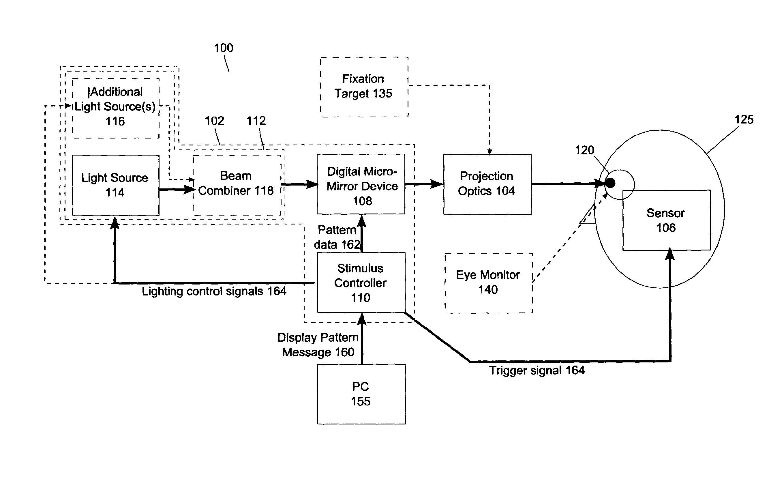
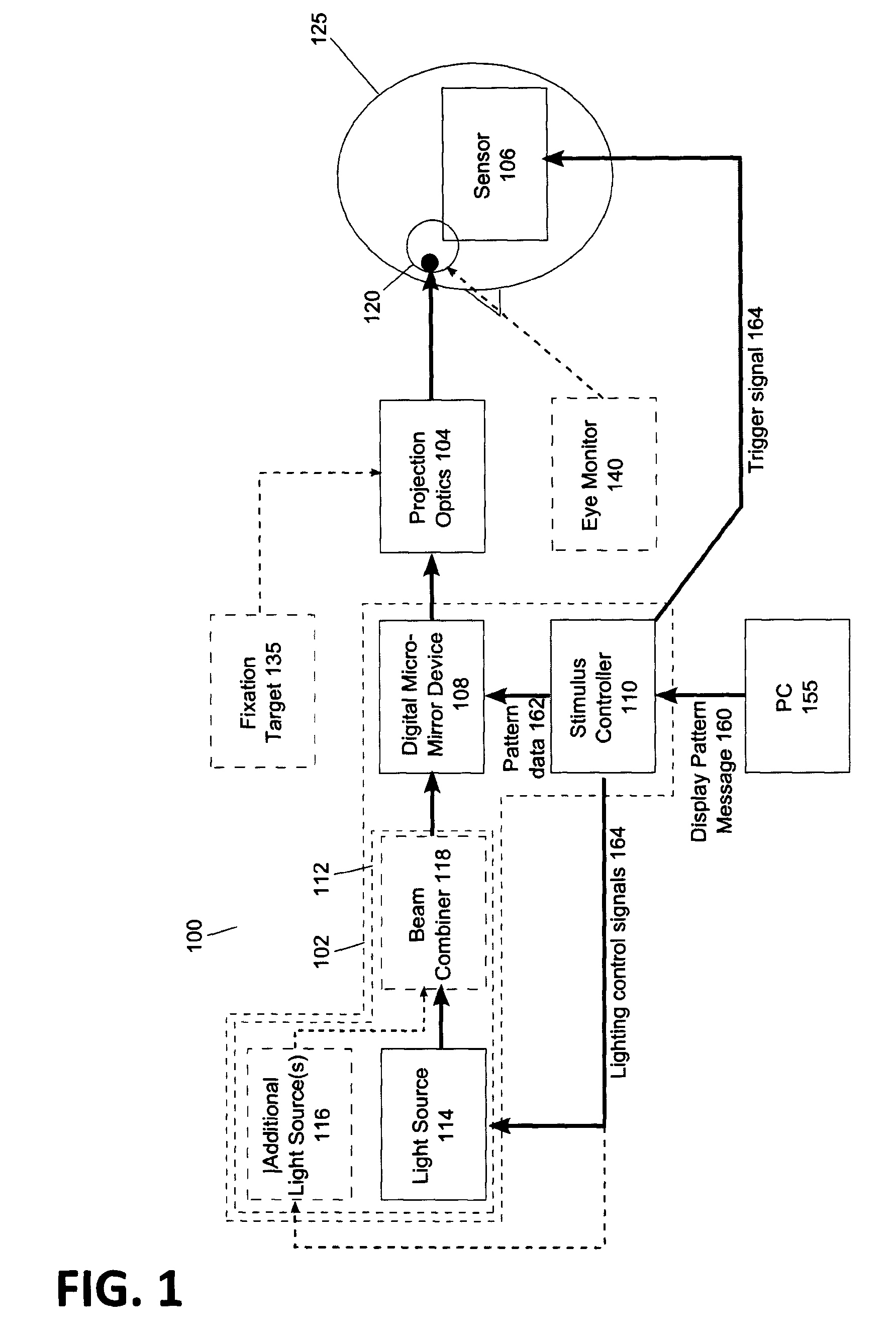
[0063]FIG. 1 illustrates a specific embodiment of a system 100 for assessing retinal functionality. The system 100 comprises an optical stimulator 102 (was 105, 145, 150, 110) for producing one or more stimulus patterns to input light, projection optics 104 (115) for projecting images of the stimulus pattern(s) onto a retina of an eye 120 of a subject 125 and a sensing unit 106 (was 130) for sensing responses evoked by the stimulus images.

[0064]As shown, the optical stimulator 102 comprises a DMD device 108 having an array of micro-mirrors (not shown) which can be switched individually in response to control signals from a controller 110. Input light for irradiating the array of micro-mirrors is provided by a light input unit 112 which comprises a light source 114 (was 105), for example a LED, coupled to the DMD device 108. Optionally, the light input unit 112 may comprise one or more additional light sources for emitting light having a different wavelength to that emitted by light ...


PUM


Abstract

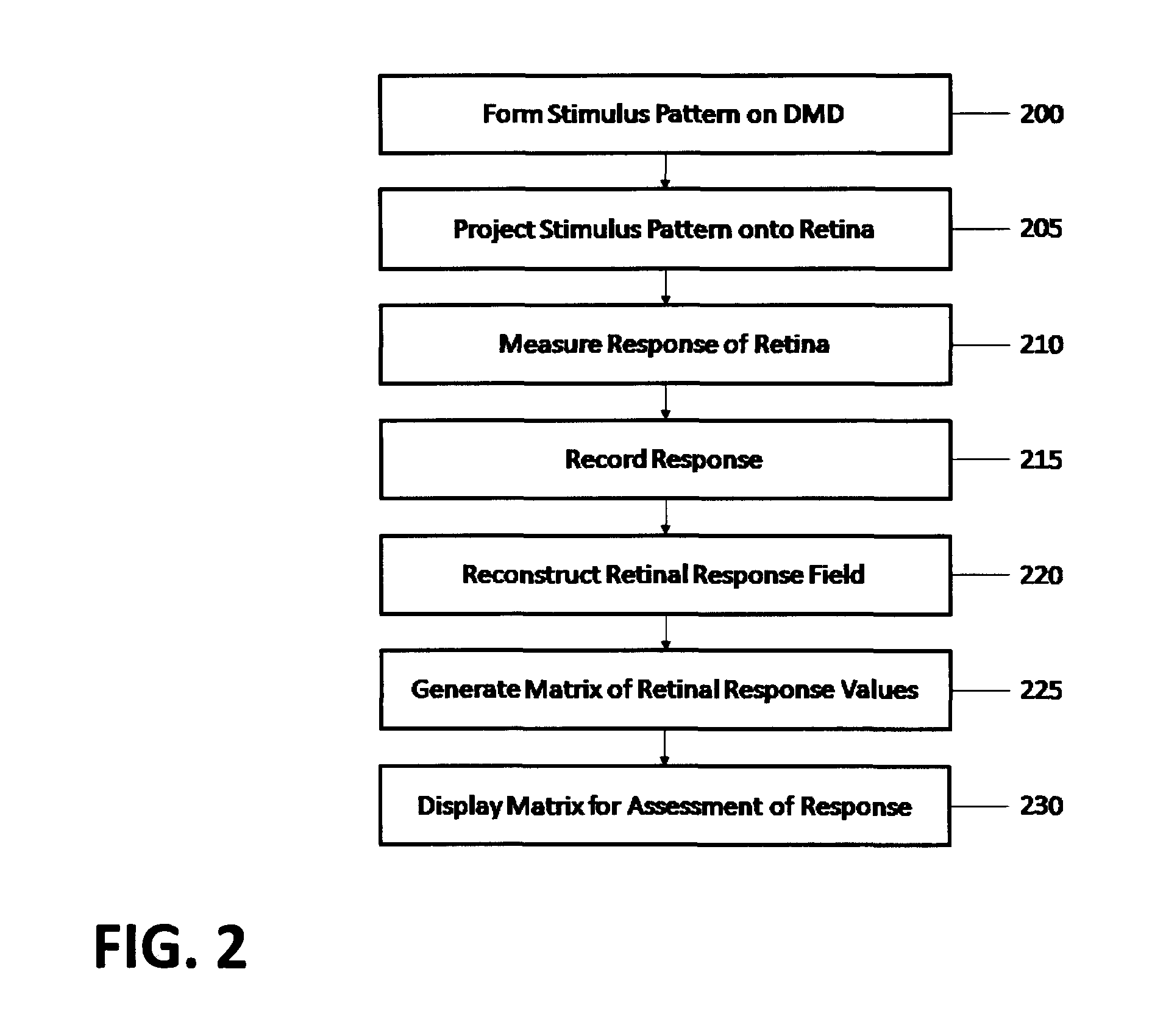
A system and method for assessing the functionality of a visual system of the eye using a digital micro-mirror device (DMD) to generate a coded pattern which is illuminated by a light source. Optics project an image of the coded pattern onto the retina of the eye. Sensors detect electrical signals based on the response of the visual system to the image. One or more processors control the DMD and correlate the electrical response from the sensor with the coded DMD pattern to assess the functionality of the visual system.

Description

CROSS-REFERENCE TO RELATED APPLICATIONS[0001]This application is related to and claims priority from U.S. Provisional patent application No. 61 / 535,693 filed 16 Sep. 2011, the entire contents of which are incorporated herein by reference.TECHNICAL FIELD[0002]This invention relates to systems and methods for assessing functionality of the retina and associated parts of the visual system using an optical stimulator device, and finds application in the fields of medicine and clinical research, especially electrophysiology and psychophysics. The invention also relates to optical stimulators for use in such systems and methods.BACKGROUND[0003]Optical stimulators are widely used to generate patterns of light for illumination of the retina of a subject. For convenience, in this specification, the term “optical stimulator” will be used to embrace stimulators emitting either visible or non-visible light, or both. The subject's response to the stimulus may be conscious or not. For example, th...

Claims


Application Information

Patent Timeline
Patent Type & Authority Patents(United States)
IPC IPC(8): A61B3/10A61B3/12A61B3/00A61B5/0484
CPCA61B3/0041A61B3/0008A61B3/12A61B5/04842A61B2576/02A61B5/378
Inventor BOATE, ALANGRIBBEN, JEREMY LLOYD
Owner ANNIDIS
Learn More