Variable capacity multiple-leg packed separation column

a packed column and multi-leg technology, applied in the field of construction and operation of packed columns, can solve the problems of increasing the amount of water produced and therefore present in the gas phase, the inability to reduce the flow of gas into the packed column, and the complexity of the design of the water separation unit operation for the gosp. achieve the effect of enhancing flexibility and reducing the length of the piping

Active Publication Date: 2016-11-01
SAUDI ARABIAN OIL CO
View PDF2 Cites 19 Cited by
  • Summary
  • Abstract
  • Description
  • Claims
  • Application Information

AI Technical Summary

Benefits of technology

[0046]In one aspect of the present invention, the economics of constructing the assembly of tubular members takes into account the favorable economies of using standard pipe lengths that are readily available from manufacturers / suppliers. The piping can be cut into any desired length, provided with appropriate openings for the introduction and removal of packing materials, the placement and welding of internal elements, the placement of ports, e.g., threaded inlets and outlets, sensors, gauges and other desired control elements. The pipes can be closed with end caps or plates, e.g., by welding, and the caps or plates are also fitted with appropriate inlet and outlet couplings for attachment of standard piping and valves. With these considerations in mind, it will be seen that a convenient arrangement is four tubular members which can be compactly positioned in touching alignment or with appropriate positioning spacers so that the four tubular members can be secured together to form a unit, should that be advantageous from the standpoint of providing a unit operation. The close positioning of the four tubular members also reduces the length of piping needed to link the units with communicating conduits for sequential passage of the treated gas stream from one to another.
[0047]Similarly, placement of multiple bundles, should they be required, in close proximity to each other, will also provide efficiencies in the delivery of the lean sorbent and recovery of the rich liquid sorbent, and also in the delivery of the raw feed gas and collection of the treated gas streams.
[0048]In yet another preferred embodiment which will be described in greater detail below, an existing packed column of the prior art, e.g., as described in conjunction with FIG. 1, which is unable to produce a product meeting specifications because of unanticipated loads in the raw feed gas is retrofitted by removing the packing section and all of the associated internal elements and installing a plurality of tubular members assembled into bundles and placed inside of the existing pressure vessel. This retrofitting with the requisite number of tubular members adapted for sequential passage of the treated stream through two or more of the small packed columns results in enhanced flexibility and the ability to recover a product stream that meets the specification.

Problems solved by technology

The design of a water separation unit operation for a GOSP can be complex.
As a result, as the well matures, the amount of water produced and therefore present in the gas phase may increase significantly and at some point exceed the capacity of the packed column to reduce the water load and achieve the desired specification in the treated gas stream.
As will be understood by those of ordinary skill in the art, it is often not possible to reduce the flow of the gas stream into the packed column because of the continuous nature of the production and / or processing operations up and downstream from the packed column.
A further problem addressed is the reconfiguration or retrofitting of an existing separator unit operation that can no longer meet treated feed specifications due to changes in the incoming feed without incurring the major capital expenses associated with installing an entirely new separator unit in an existing larger complex unit operation.

Method used


Image

  • Variable capacity multiple-leg packed separation column
  • Variable capacity multiple-leg packed separation column
  • Variable capacity multiple-leg packed separation column

Examples


case study

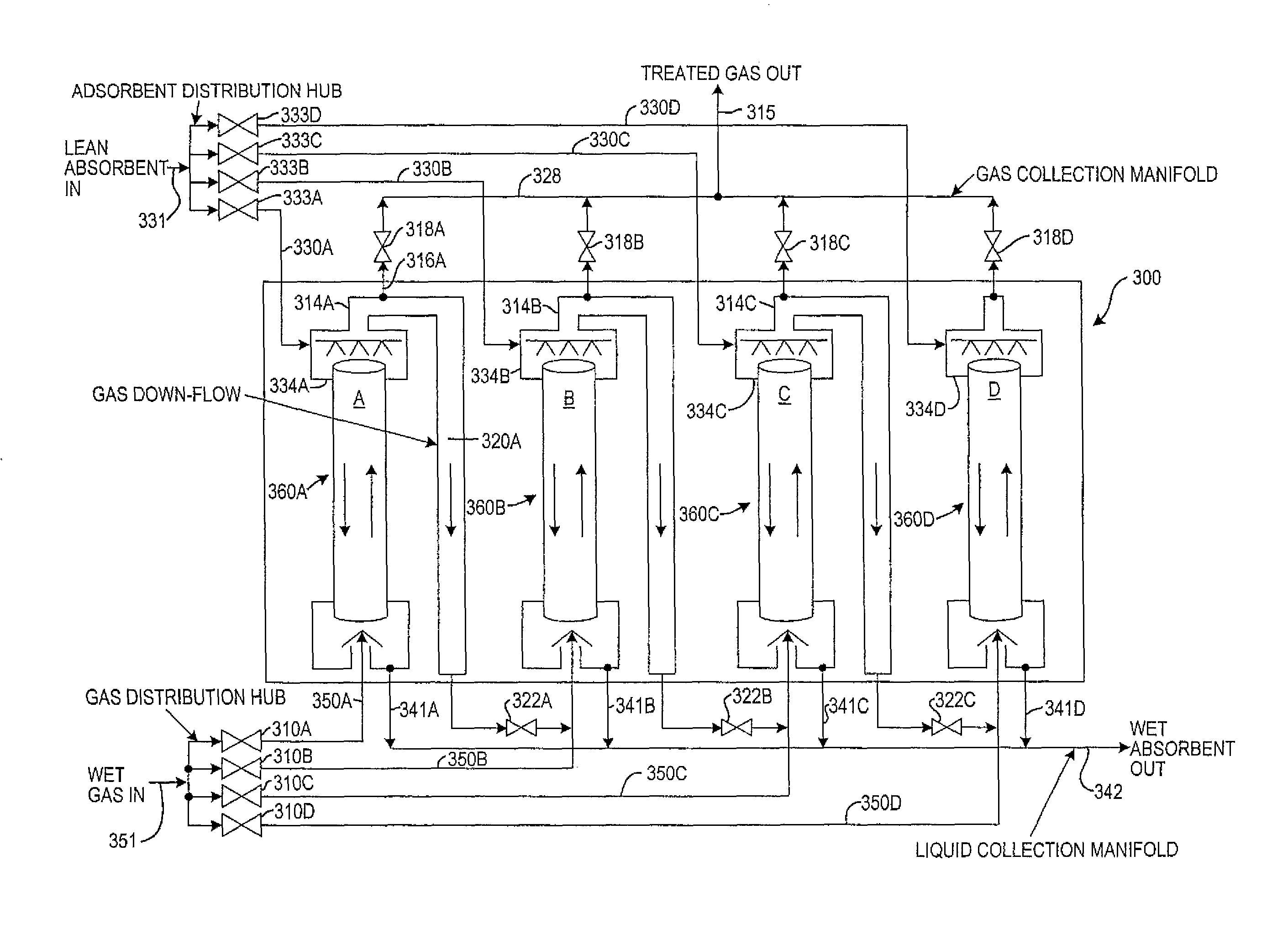
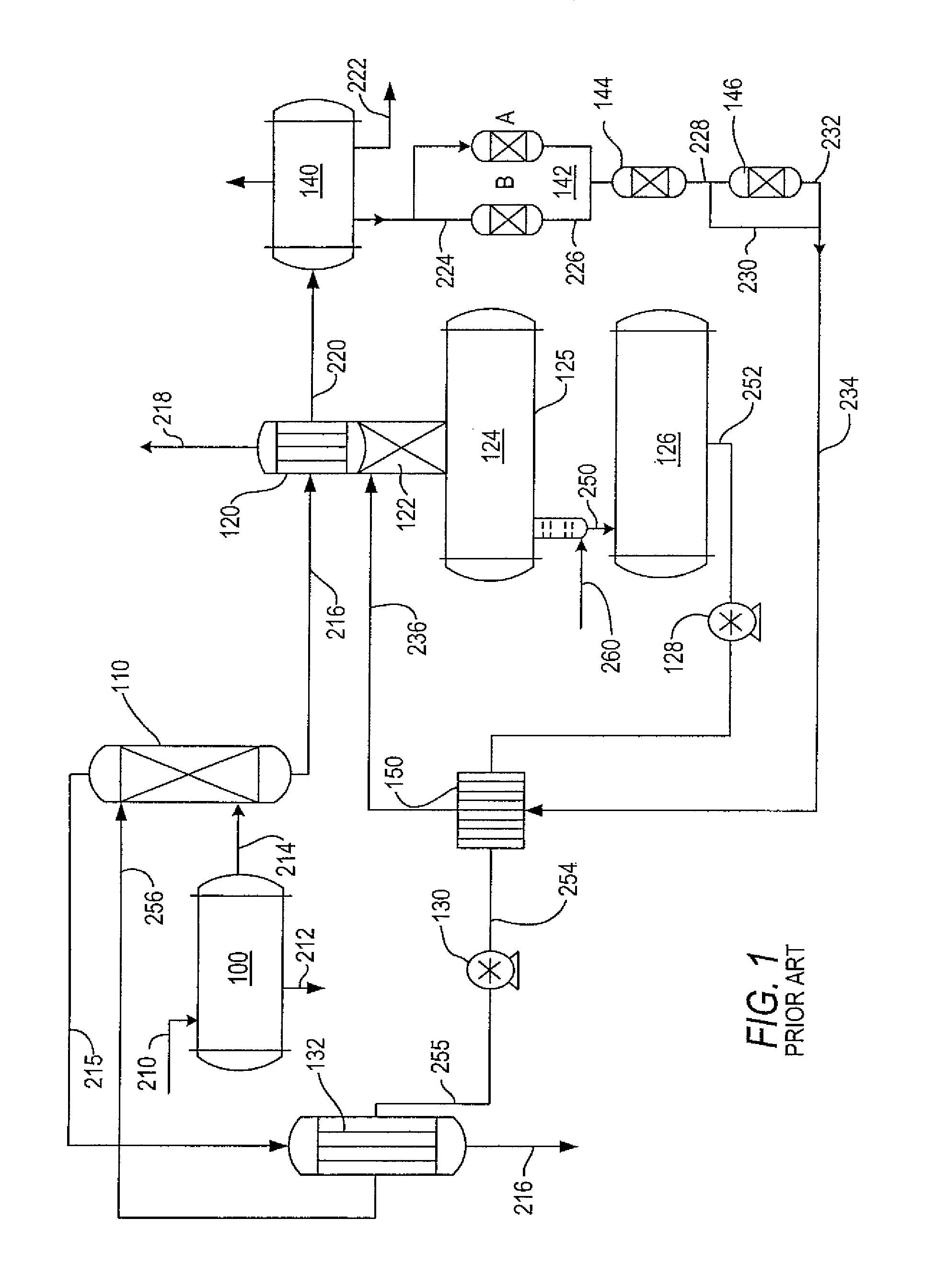
[0069]A working gas-oil separation plant (GOSP) included a gas dehydration unit that was designed with a theoretical capacity for dehydrating 511.2 MMSCFD (million standard cubic feet per day) gas to a maximum water load of 7 pounds of water per MMSCF of wet gas by a physical absorption process using triethylene glycol (TEG) in a packed column contactor. The water-rich TEG was regenerated and continuously recycled back for reuse in the system. The full process description and the flow scheme of the GOSP gas dehydration unit of the invention is summarized in FIGS. 1 and 7A and 7B below.

[0070]Subsequent to the commissioning and the initial satisfactory operation of the TEG dehydration unit to meet treated gas stream specifications, it was found that the separator was no longer able to dehydrate the wet gas to the required specification at the design gas flowrate. This was due to the significant departure from the contemplated design operating conditions. As shown by the design basis v...


PUM

PropertyMeasurementUnit
pressureaaaaaaaaaa
diameteraaaaaaaaaa
diameteraaaaaaaaaa

Abstract

An industrial packed column for gas stream processing to remove a component by liquid absorbent contact includes:a. a plurality of packed tubular members having ends aligned in vertical parallel array to form a first bundle,b. an upper lean absorption liquid inlet and lower rich absorption liquid outlet;c. a raw gas feed inlet positioned below the packing material, connected to a raw feed gas manifold via control valves for selectively admitting the feed gas to one or more of the plurality of tubular members,d. an upper treated gas outlet, connected via valved conduit to (i) a treated gas collection manifold and (ii) the raw gas inlet of one or more of the other tubular members, andthe apparatus equipped with appropriate systems so that desired portions of the treated gas stream exiting a tubular member can be passed for further treatment to at least one other tubular member in the first bundle.

Description

BACKGROUND OF THE INVENTION[0001]1. Field of the Invention[0002]The present invention relates to the construction and operation of packed columns used in separation processes such as absorption, stripping and distillation.[0003]2. Description of Related Art[0004]Packed columns are utilized as unit operations for performing separation processes such as absorption, stripping and distillation where there is a need to achieve mass transfer between gas and liquid phases. For example, in the absorption process, the packed column typically is used to remove a component from a gas stream by contact with a liquid sorbent.[0005]In the oil and gas, and chemical processing industries, the separation process is often carried out to meet a predetermined product specification. One widely used application of the packed column is the removal of water from a gaseous hydrocarbon stream in conjunction with a gas-oil separation plant, or GOSP. During the production life of a well, the mix of crude oil a...

Claims


Application Information

Patent Timeline
Patent Type & Authority Patents(United States)
IPC IPC(8): B01D53/14B01D53/26
CPCB01D53/263B01D2252/2023B01D2252/20489B01D2252/504B01D2257/80B01D53/1412B01D53/1493B01D53/18
Inventor SALU, SAMUSIDEEN ADEWALEZAHRANI, TALAL A.
Owner SAUDI ARABIAN OIL CO
Why Eureka
Try Eureka