
Oscilloscope with logic analyzer frontend

a logic analyzer and oscilloscope technology, applied in the field of oscilloscopes, can solve the problems of affecting the test throughput, affecting the test results, and reducing the associated cost, so as to improve the test throughput and reduce the effect of the cos

Active Publication Date: 2016-11-01
ROHDE & SCHWARZ GMBH & CO KG +1
View PDF10 Cites 6 Cited by
  • Summary
  • Abstract
  • Description
  • Claims
  • Application Information

AI Technical Summary

Benefits of technology

The present invention provides a measurement system and related methods for testing multiple mobile phones in parallel, which improves test throughputs and reduces costs. The system measures various parameters of a transmitted signal that is received by the mobile phone, such as signal amplitude, signal timing, and signal quality. The system uses a digital comparator and a digital correction unit to adjust the comparator's decision threshold value. The system also includes an analog-to-digital converter with a higher bit resolution for better accuracy. The invention allows for easier handling of signal corrections and improved accuracy in the presence of distorted signals or corrupted data.

Problems solved by technology

Using such a discretization technique has the technical drawback that all amplitude information of the applied signal is lost.
Current oscilloscope / MSO approaches, however, still present drawbacks with regard to the distortion of the applied signal, and adjustment of a threshold level and compensation for MSO and probe-generated errors and losses.

Method used


Image

  • Oscilloscope with logic analyzer frontend
  • Oscilloscope with logic analyzer frontend
  • Oscilloscope with logic analyzer frontend

Examples


Embodiment Construction

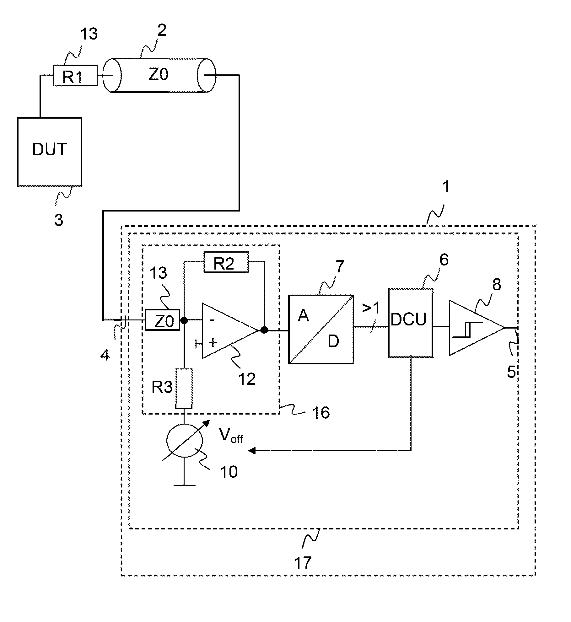
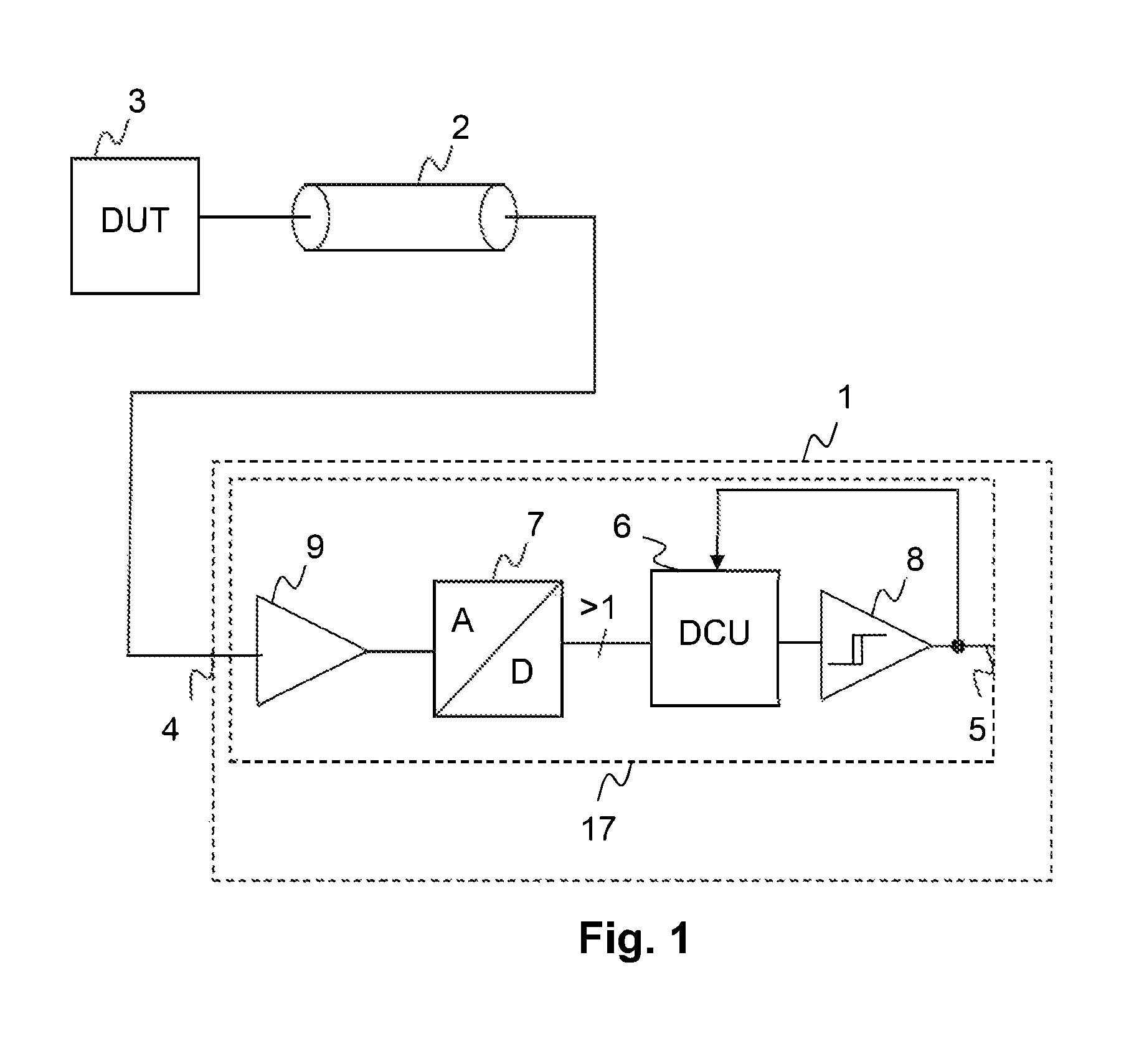
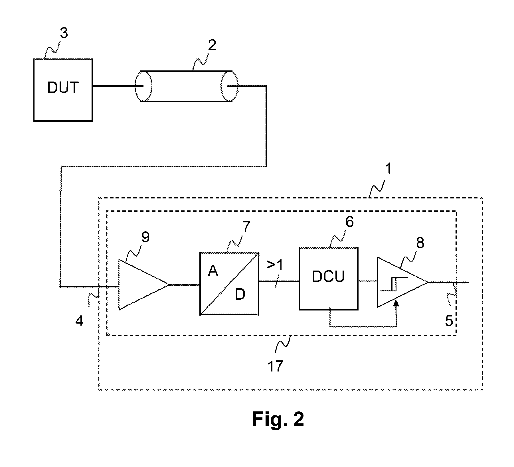
[0036]FIG. 1 illustrates a block diagram of a first example oscilloscope according to example embodiments. The oscilloscope 1 is connected to a DUT 3 using a measurement probe 2. The oscilloscope 1 comprises at least a digital input port 4 on which a digital signal is applied that is generated by the DUT 3. The oscilloscope 1 is preferably an MSO. Thus, the oscilloscope 1 comprises a logic analyzer frontend 17 that comprises an input amplifier 9 for buffering the applied digital signal. Subsequent to the digital input port 4, an analog-to-digital converter 7, short ADC, is arranged in the signal path. The output of the ADC 7 comprises more than one signal lines to indicate that an ADC's bit resolution is higher than two bit, preferably four bit, more preferably eight bit.

[0037]The output of the ADC 7 is applied to a digital correction unit 6, short DCU. Subsequent to the DCU 6, a digital comparator 8 is arranged in the signal path. The output of the digital comparator 8 provides an ...


PUM


Abstract

An electronic test apparatus, such as an oscilloscope, comprising a logic analyzer frontend, wherein the logic analyzer frontend comprises a digital input port configured to receive a digital signal from a device under test. The logic analyzer frontend further comprises at least one analog-to-digital converter that is arranged downstream of the digital input port, and a digital comparator that is arranged downstream of the analog-to-digital converter. The digital comparator is configured to generate an adjusted digital signal and to provide the adjusted digital signal to further components of the electronic test apparatus. The logic analyzer frontend further comprises a digital correction unit configured to adjust a digital decision threshold value of the comparator.

Description

RELATED APPLICATIONS[0001]This application claims the benefit of the earlier filing date under 35 U.S.C. §119(e) of U.S. Provisional Application Ser. No. 62 / 184,852 (filed 2015 Jun. 25).FIELD OF THE INVENTION[0002]Embodiments of the present invention relate to oscilloscopes that comprise a logic analyzer frontend, and more specifically to a mixed signal oscilloscope (MSO). MSOs combine the functionality of a digital storage oscilloscope with the functionality of a logic analyzer, with benefits that include the ability to view analog and digital signals together in time, and to trigger on either digital or analog signals and capture on the other. The digital input ports are used for applying at least one digital signal that is analyzed and evaluated in view of its logic characteristics.BACKGROUND OF THE INVENTION[0003]A classical logic analyzer is an electronic instrument that captures and displays multiple digital signals from a digital system or digital circuit, hereinafter referre...

Claims


Application Information

Patent Timeline
IPC IPC(8): H03M1/06H03M1/18
CPCH03M1/0609H03M1/188G01R13/0254
Inventor PESCHKE, MARTIN
Owner ROHDE & SCHWARZ GMBH & CO KG
Learn More