Methods for controlling electrical inverters and electrical inverters and systems using the same

a technology of electrical inverters and electrical inverters, applied in the direction of reactive power adjustment/elimination/compensation, single network parallel feeding arrangement, energy industry, etc., can solve the problems of inverter units becoming less efficient and power (ap) delivered to load must be decreased, so as to achieve the effect of maximizing inverter efficiency

Inactive Publication Date: 2016-11-08
AEG POWER SOLUTIONS BV
View PDF15 Cites 1 Cited by
  • Summary
  • Abstract
  • Description
  • Claims
  • Application Information

AI Technical Summary

Benefits of technology

[0014]The principles of the present invention are embodied in systems and methods for controlling an inverter output current in response to the grid voltage and the requested output power to be delivered to an electrical grid. In one particular embodiment, both the inverter output current amplitude and phase lag are controlled to control the amount of both AP and RP delivered to the grid. In an alternate embodiment, the inverter is configured to deliver only AP to maximize inverter efficiency. In addition, the principles of the present invention allow for the copying of the shape of the grid voltage waveform such that the inverter behaves similar to a resistor to the extent that the voltage and current are proportional.

Problems solved by technology

However, if the load is not a purely resistive, and hence the current and voltage are not in phase, the power must be delivered to the load as active and reactive parts.
To process the Reactive Power (RP), the Active Power (AP) delivered to the load must be decreased and the inverter unit becomes less efficient.

Method used


Image

  • Methods for controlling electrical inverters and electrical inverters and systems using the same
  • Methods for controlling electrical inverters and electrical inverters and systems using the same
  • Methods for controlling electrical inverters and electrical inverters and systems using the same

Examples


Embodiment Construction

[0024]The principles of the present invention and their advantages are best understood by referring to the illustrated embodiment depicted in FIGS. 2-5 of the drawings, in which like numbers designate like parts.

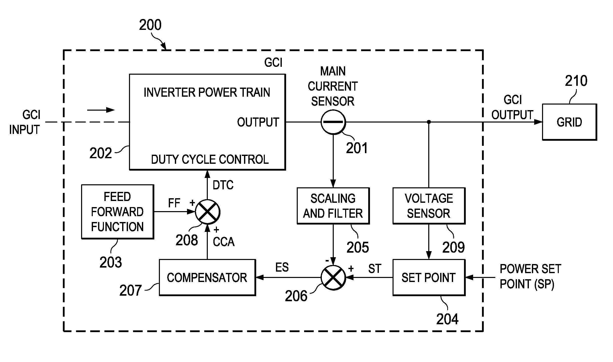
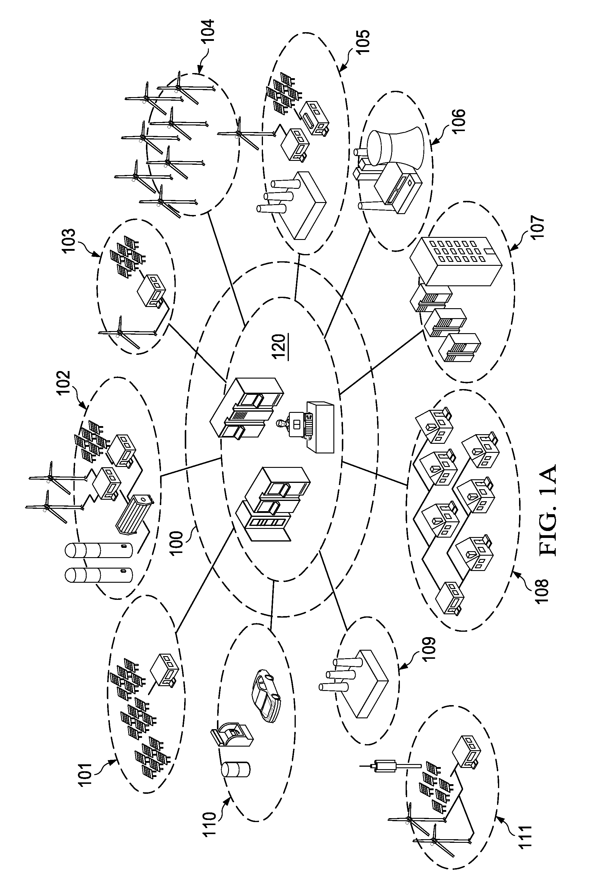
[0025]FIG. 2 is a block diagram of an exemplary Grid Connected Inverter (GCI) 200 according to one embodiment of the present inventive principles. GCI 200 can advantageously be applied to the systems and subsystems shown in FIG. 1A, including the inverters, uninterrupted power supply (UPS) systems, and AC / DC converters, among others.

[0026]In the embodiment of FIG. 2, a Main Current Sensor 201 senses the current delivered to electrical grid 210 from an Inverter Power Train 202. In some embodiments, such as GCI 300 shown in FIG. 3, an Auxiliary Current Sensor 301 is also provided to sense the inductor current through embodiments of Inverter Power Train 202 having multiple filtering stages or cells. (When multiple filter stages / cells are used, the current phase lag observed at ...


PUM


Abstract

A system for generating a duty cycle control signal for controlling an inverter power train providing an output current waveform to a grid operating with a grid voltage waveform compares a reference current waveform shaped to the grid voltage waveform with the output current waveform to generate an error signal. The error signal is used to generate a corrective control action signal, which is combined with a feed-forward signal representing a nominal duty cycle generated with a feed-forward function. The combination of the feed-forward signal and the corrective control action signal provide the duty cycle control signal.

Description

CROSS-REFERENCE TO RELATED APPLICATION[0001]The present application claims the benefit of U.S. Provisional Patent Application Ser. No. 61 / 749,438, filed Jan. 7, 2013.FIELD OF INVENTION[0002]The present invention relates in general to electrical inverters, and in particular, to methods for controlling electrical inverters and systems using the same.BACKGROUND OF INVENTION[0003]In a traditional electrical utility grid model, the voltage and associated current are provided by large scale utility power plants running from expendable energy sources, such as coal, nuclear, natural gas and oil. However, modern electrical utility grids, in addition to receiving electrical power from traditional energy sources, can now also receive electrical power from multiple alternative and / or renewable energy sources, which may be directly or indirectly connected to the electrical grid. However, notwithstanding the particular types of energy sources (e.g., traditional, alternative, or renewable) providi...

Claims


Application Information

Patent Timeline
Patent Type & Authority Patents(United States)
IPC IPC(8): H02M1/12H02J3/38H02J3/18H02M7/04H02J3/48H02M7/48H02J3/40H02J3/50
CPCH02M7/48H02M7/04H02J3/1814H02J3/1835H02J3/383H02J3/386H02J3/40H02J3/48H02J3/50H02M1/12H02J3/385Y02E10/563Y02E10/58Y02E10/763Y02E40/30Y02P80/23H02J2300/40H02J2300/28H02J2300/26H02J2300/24H02J3/381H02J3/46Y02E10/56Y02E10/76Y02P80/20
Inventor BALOCCO, DIDIER
Owner AEG POWER SOLUTIONS BV
Why Eureka
Try Eureka