Microlens array, light intensity distribution uniformizing element having same, and projection apparatus having light intensity distribution uniformizing element
a technology of light intensity distribution and microlens array, which is applied in the direction of planar/plate-like light guides, instruments, radiation control devices, etc., can solve the problems of difficult to form ideal lens shapes around boundary lines between adjacent microlenses, difficult to form ideal lens shapes around the edges of adjacent microlenses, and ineffective portions that are not in ideal lens shapes. to achieve the effect of forming the portion that does not function as desirable lens
- Summary
- Abstract
- Description
- Claims
- Application Information
AI Technical Summary
Benefits of technology
Problems solved by technology
Method used
Image
Examples
first embodiment
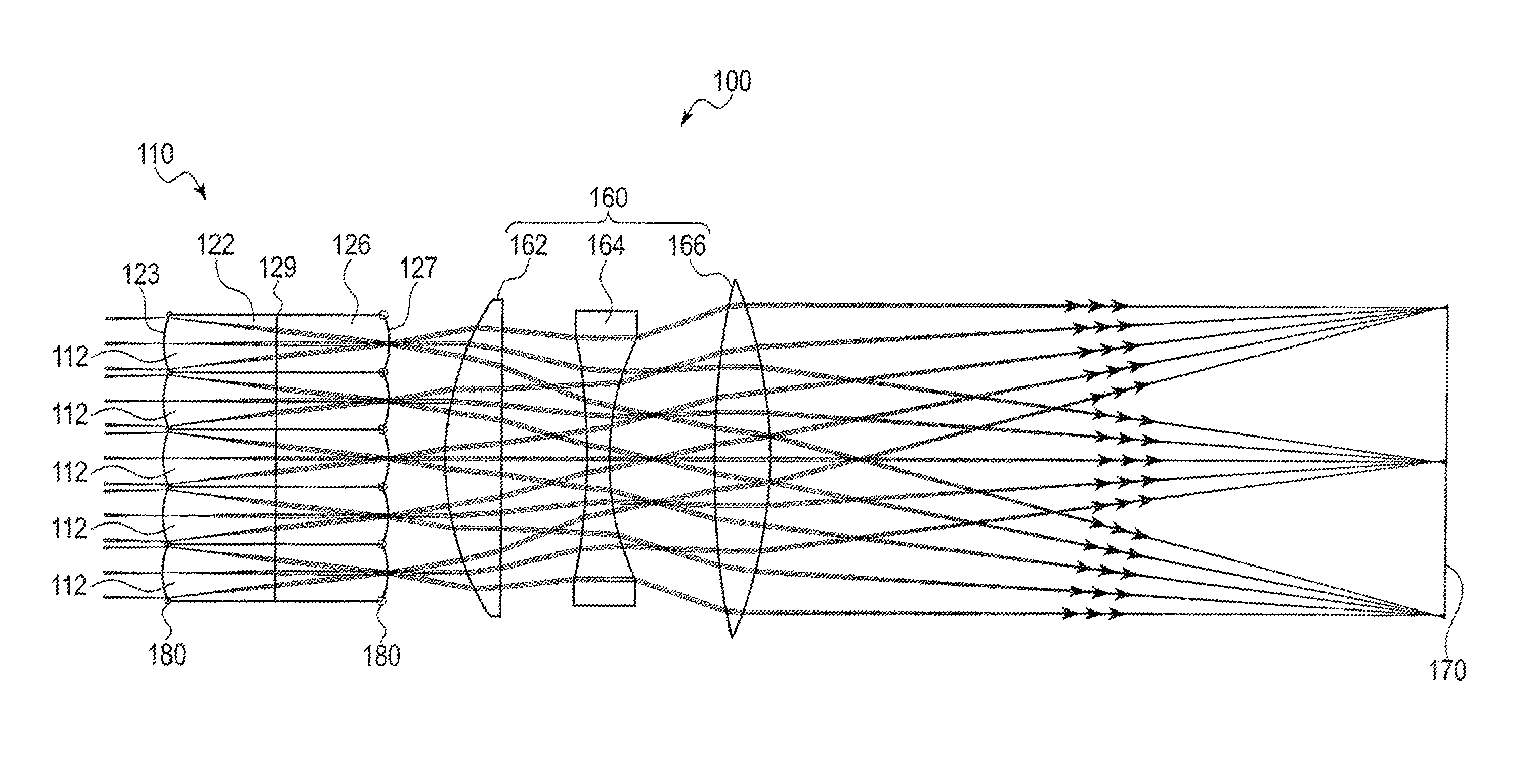
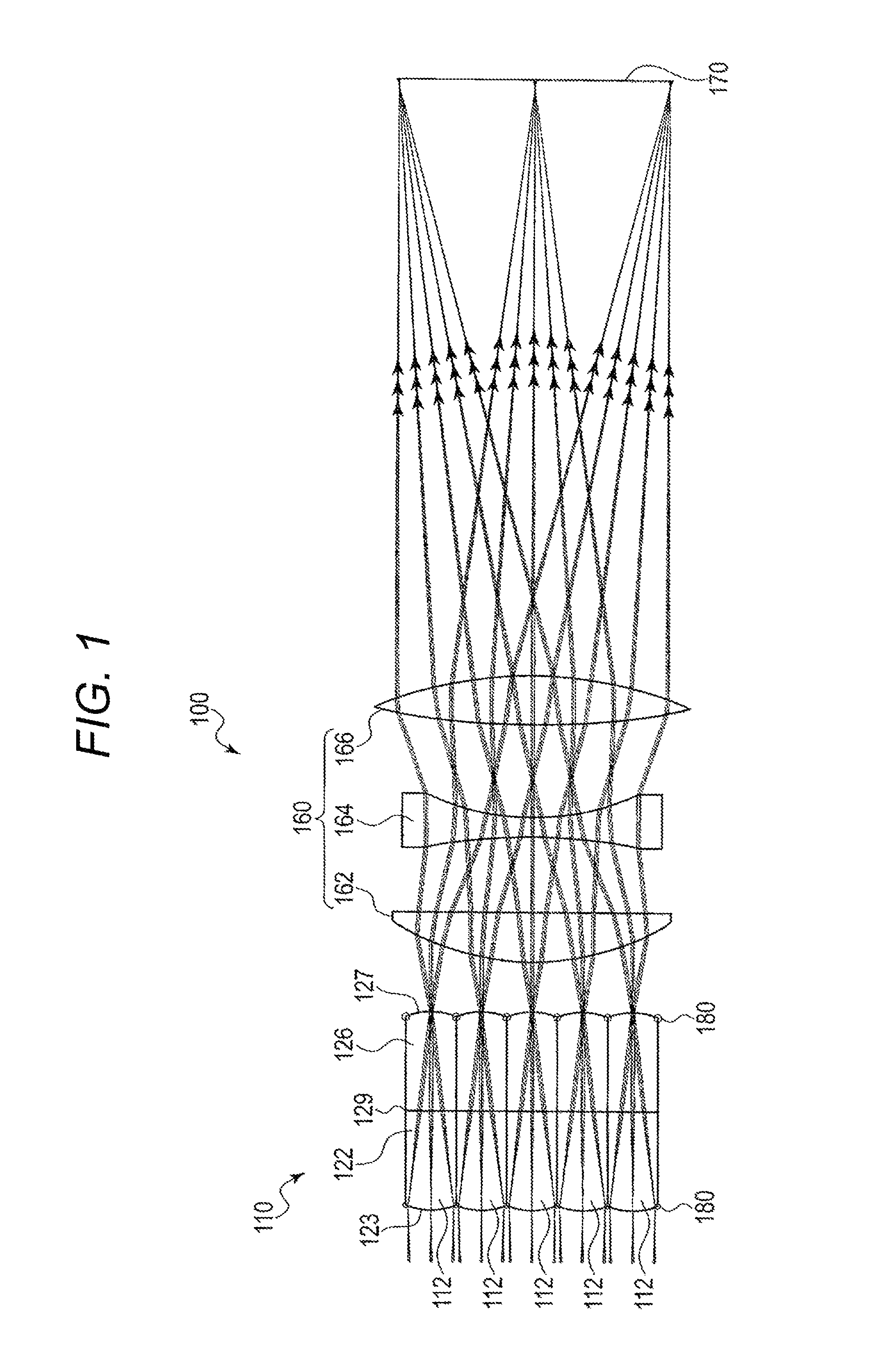
[0019]A first embodiment of the invention will be described with reference to the drawings. FIG. 1 illustrates an outline of an example structure of a light intensity distribution uniformizing element 100 according to the present embodiment. The light intensity distribution uniformizing element 100 includes a microlens array 110 and a coupling lens 160. The coupling lens 160 includes a first lens 162, a second lens 164, and a third lens 166.
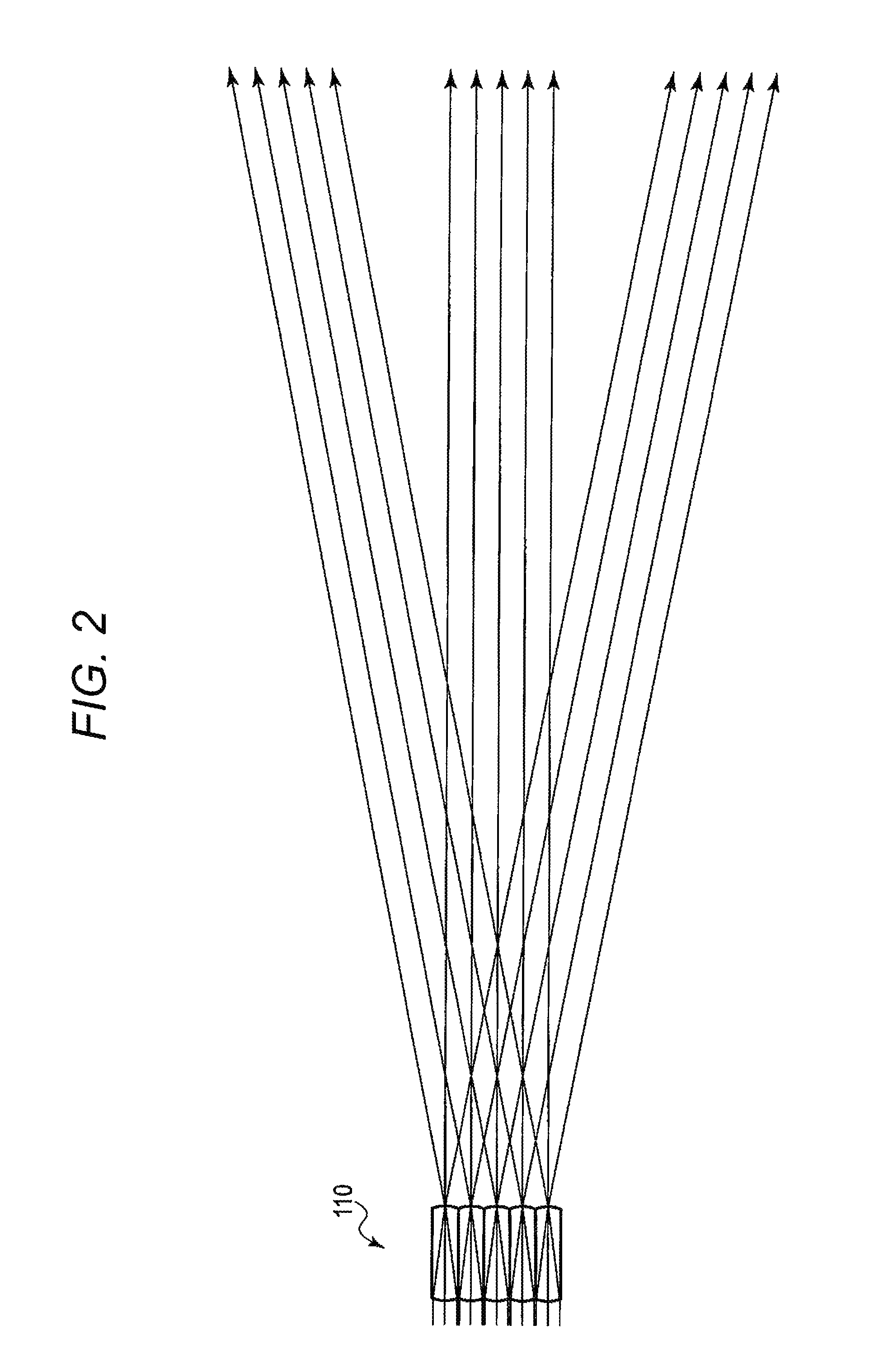
[0020]The microlens array 110 includes multiple microlenses 112. The microlenses 112 are arranged in an array on one plane in a state in which optical axes of the microlenses 112 are parallel. For example, the microlenses 112 are arranged in a rectangular grid pattern.
[0021]The microlens array 110 according to the present embodiment includes a first microlens array 122 provided on the entrance side and a second microlens array 126 provided on the exit side. The first microlens array 122 is made of resin. The second microlens array 126 is made of ...
second embodiment
[0037]A second embodiment will be described with reference to the drawings. The present embodiment is an embodiment of a projection apparatus in which the microlens array according to the first embodiment is used. FIG. 4 illustrates an outline of an example configuration of the projector 10 that is a projection apparatus according to the present embodiment. The projector 10 is a digital light processing (DLP) (registered trademark) projector using a micromirror display device. The projector 10 includes an input unit 11, an image converter 12, a projection processor 13, a micromirror device 14, a light source unit 15, a mirror 16, a projector lens unit 17, a CPU 18, a main memory 19, a program memory 20, an operation unit 21, an audio processor 22, a speaker 23, and a system bus SB.
[0038]The input unit 11 includes terminals such as a pin jack (RCA) type video input terminal and a D-sub 15 type RGB input terminal, and receives analog image signals as input. The input unit 11 converts ...
PUM
 Abstract
Description
Claims
Application Information
 - R&D
- Intellectual Property
- Life Sciences
- Materials
- Tech Scout
- Unparalleled Data Quality
- Higher Quality Content
- 60% Fewer Hallucinations
Browse by: Latest US Patents, China's latest patents, Technical Efficacy Thesaurus, Application Domain, Technology Topic, Popular Technical Reports.
© 2025 PatSnap. All rights reserved.Legal|Privacy policy|Modern Slavery Act Transparency Statement|Sitemap|About US| Contact US: help@patsnap.com


