Image forming apparatus of electrophotographic system

a technology of electrophotography and forming apparatus, which is applied in the direction of electrographic process apparatus, printing, instruments, etc., can solve the problems of aging degradation of light source, inability of the above-mentioned publication to cope with a change in driving current/light amount characteristic,

Active Publication Date: 2016-11-22
CANON KK
View PDF3 Cites 0 Cited by
  • Summary
  • Abstract
  • Description
  • Claims
  • Application Information

AI Technical Summary

Benefits of technology

[0009]The present invention provides an image forming apparatus that is capable of controlling a light amount of a light beam to which a photosensitive member is exposed to be a target light amount even when an emission characteristic of a light source varies.

Problems solved by technology

However, the technique of the above-mentioned publication cannot cope with a change of the driving-current / light-amount characteristic due to a temperature change around the light source, a temperature change of the light source due to heat generation of the light source itself, or aging degradation of the light source that is caused by repeating emissions.

Method used


Image

  • Image forming apparatus of electrophotographic system
  • Image forming apparatus of electrophotographic system
  • Image forming apparatus of electrophotographic system

Examples


first embodiment

[0039]Hereafter, embodiments according to the present invention will be described in detail with reference to the drawings. First, an image processing apparatus will be described.

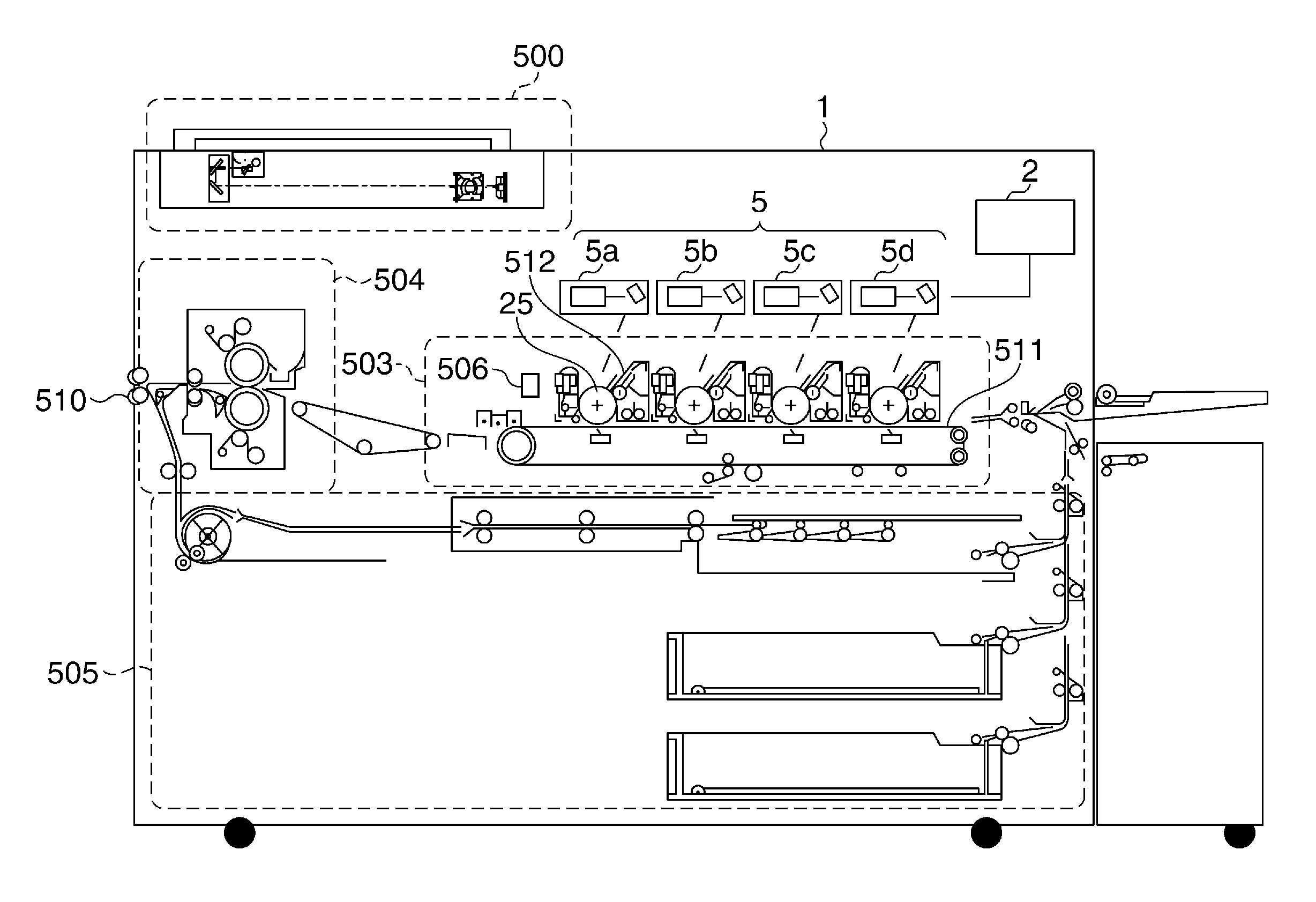
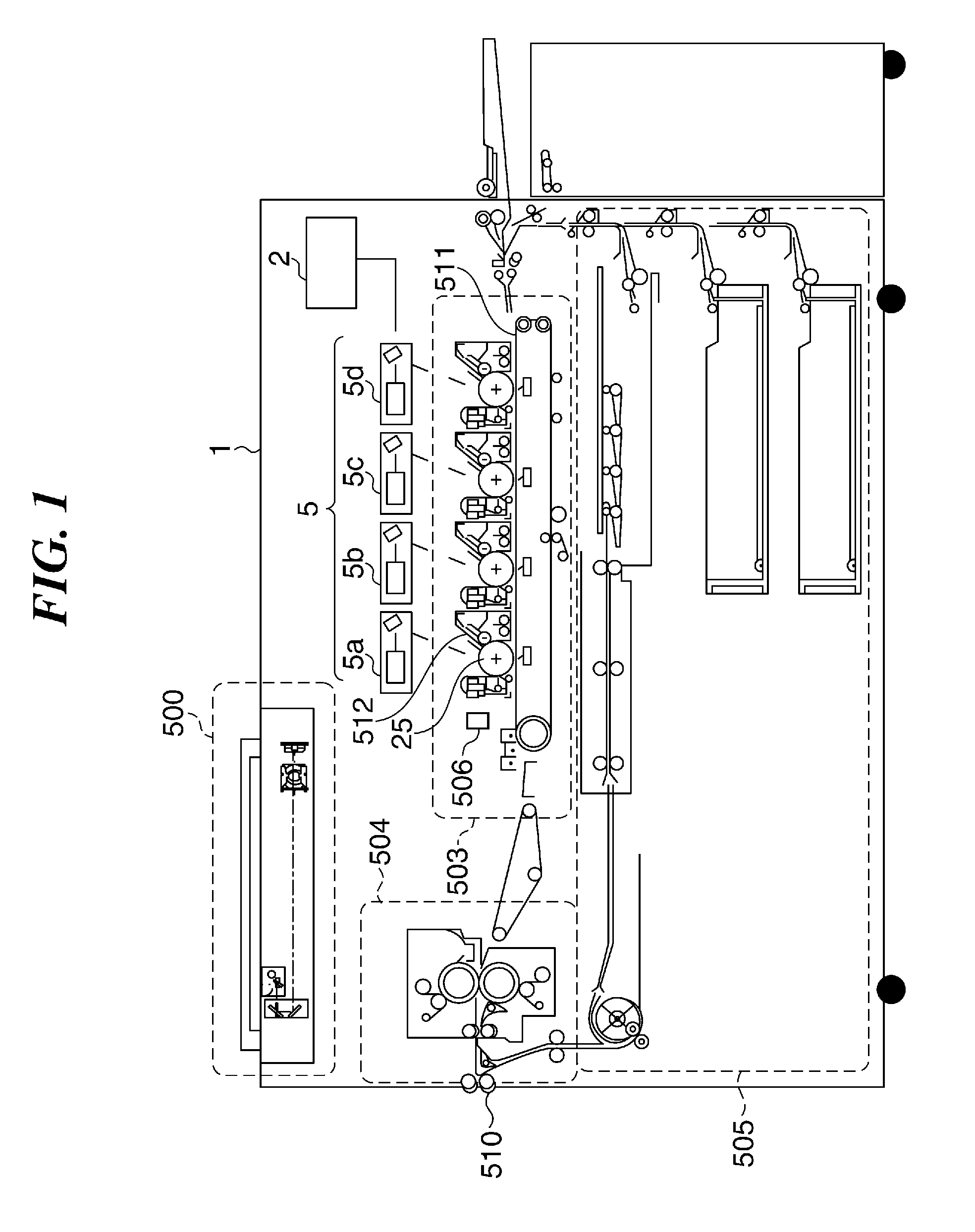
[0040]FIG. 1 is a sectional view schematically showing the image forming apparatus 1. The image forming apparatus 1 includes a reader-scanner section 500, an image control unit (a determination unit) 2, an exposure section 5, an image forming section 503, a fixing section 504, and a sheet feeding section 505.

[0041]The reader-scanner section 500 irradiates an original placed on a tray with a light, and reads an original image optically by receiving a reflected light from the original.

[0042]The image control unit 2 controls light amounts of light beams (laser beams) emitted from the exposure section 5, and generates image data by converting the original image read with the reader-scanner section 500 into electrical signals. The exposure section 5 includes optical scanning devices 5a, 5b, 5c, and 5d that form...

second embodiment

[0115]Next, an image processing apparatus according to the present invention will be described.

[0116]Since the second embodiment is basically identical to the first embodiment in its configurations and actions, descriptions about the identical configurations and actions are omitted, and configurations and actions that are different from that in the first embodiment will be described in detail.

[0117]FIG. 12A is a flowchart showing procedures of an adjustment process according to the second embodiment.

[0118]The adjustment process in FIG. 12A is performed when the laser control unit 52 drives the laser driving unit 11 with a control signal.

[0119]In the adjustment process in FIG. 12A, an inspection process in the ADC 54 is performed in addition to the adjustment process in FIG. 6. The ADC 54 controls a digital signal (a driving current is also included) outputted on the basis of an analog signal (a driving current is also included). The ADC 54 tends to be affected by an ambient temperat...

third embodiment

[0138]Next, an image processing apparatus and a control method therefor according to the present invention will be described.

[0139]Since the third embodiment is basically identical to the first embodiment in its configurations and actions, descriptions about the identical configurations and actions are omitted, and configurations and actions that are different from that in the first embodiment will be described in detail.

[0140]FIG. 15 is a block diagram schematically showing a configuration of a laser control system 300 in the image forming apparatus 1 according to the third embodiment of the present invention. It should be noted that only different configurations from the laser control system 300 in FIG. 3A will be described in detail.

[0141]As shown in FIG. 15, the ADC 54 and the gain correction unit 53 are disposed in the laser driving unit 11, and a PD sample hold circuit (hereinafter referred to as “PD_SH”) 71 is also disposed in the laser driving unit 11. The PD_SH 71, the ADC ...


PUM


Abstract

An image forming apparatus capable of controlling an amount of light beam to be a target value even when an emission characteristic of a light source varies. A photosensitive member is exposed to the light beam emitted form a light source. A light receiving element receives the light beam. Voltage for prescribing the driving current is set in a voltage setting unit. A voltage control unit controls the voltage so that the light amount of the light beam received by the light receiving element becomes a target light amount. A determination unit determines a correction parameter for correcting the voltage based on at least the voltage set in the voltage setting unit. A correction unit corrects the voltage set in the voltage setting unit with the correction parameter. A current supply unit supplies a driving current corresponding to the corrected voltage to the light source based on image data.

Description

BACKGROUND OF THE INVENTION[0001]1. Field of the Invention[0002]The present invention relates to an image forming apparatus of an electrophotographic system and, in particular, to a technique for controlling a light amount of a light beam emitted from a light source.[0003]2. Description of the Related Art[0004]The image forming apparatus of the electrophotographic system is provided with a light source (for example, an LED, a semiconductor laser) for exposing a photosensitive member. The image forming apparatus controls a driving current supplied to the light source so that an output image is formed with a desired density.[0005]Japanese Laid-Open Patent Publication (Kokai) No. 2000-351232 (JP 2000-351232A) discloses a technique that stores a driving-current / light-amount characteristic (a light-amount / current characteristic curve) to a nonvolatile memory for every LED and controls a light amount of a light beam emitted from each LED on the basis of the driving-current / light-amount ch...

Claims


Application Information

Patent Timeline
Patent Type & Authority Patents(United States)
IPC IPC(8): G03G15/043B41J2/47
CPCG03G15/043B41J2/47
Inventor SEKI, YUICHI
Owner CANON KK
Why Eureka
Try Eureka