Distance measurement by beating a varying test signal with reference signal having absolute frequency value predetermined with a specified accuracy

a technology of distance measurement and reference signal, applied in the direction of measurement device, electromagnetic wave reradiation, instruments, etc., can solve the problems of inability of modern measurement system to measure such signals with required accuracy, and the stability of typical commercial lasers or fiber lasers only exists

Active Publication Date: 2016-11-29
MAGIQ TECH INC
View PDF1 Cites 0 Cited by
  • Summary
  • Abstract
  • Description
  • Claims
  • Application Information

AI Technical Summary

Benefits of technology

[0008]Furthermore, it is desirable to achieve this level of measurement accuracy without reliance on any mechanical references, while avoiding fringe counting allowing the measurements to be interrupted. Such a method is particularly suited for measurements that must be taken with extremely high accuracy over long periods of time, such as measuring tectonic drift or volcanic activity with laser rangefinders, monitoring tiltmeters to observe the effects of prolonged underground activity, e.g., from construction projects, oil and gas production, or ground-water usage, or long-term data collection from any sensors which can be interrogated by measuring distances optically. In addition, performing the measurement without requiring accurate prior knowledge of an earlier position measurement enables the applications where multiple sensors are interrogated for an extended period of time by a single interrogating system.
[0012]For example, by interfering two signals of sufficiently high, but comparable frequencies, the resulted modulated signal includes a high frequency component. i.e., a carrier signal with a frequency representing an average of the frequencies of the two interfered signals, that is distinguishable from a low frequency component of the modulated signal, i.e., a modulation signal with a beat frequency representing a difference between the frequencies of the two interfered signals. Thus, the beat frequency of the low frequency component is measurable and can be used in measuring and analyzing high frequency signals. Accordingly, if the frequency of one of the high frequency signals is known with specified accuracy, that known frequency can be used as a reference to determine the unknown frequency of another signal. Also, if the known frequency is selected sufficiently close to the unknown frequency, the low frequency component can be accurately measured with available commercial detectors, and thus the total cost of the measurements can be reduced.
[0014]In one embodiment, a laser is stabilized to an atomic or molecular reference, using sub-Doppler spectroscopy. Properly implemented, this can allow absolute wavelength accuracy of an inexpensive laser to a part in 10^9 as long as the wavelength matches an appropriate transition. Furthermore, the locked wavelength does not change with temperature, mechanical alignment, or conditions of the reference cell, and there are rarely additional transitions close enough in frequency to offer any ambiguity over which line is locked.

Problems solved by technology

However, a number of modern measurement systems are incapable of measuring such signals with required accuracy.
In addition, a typical commercial laser or fiber laser is only as stable as its cavity size, which changes with temperature, current, gain medium aging and mechanical strain, all of which can change over time, especially in the presence of environmental disturbances.
The manufacturing variability of any laser model is also of concern, requiring each device to be independently characterized under operating conditions before any accuracy in wavelength can be obtained, which is rarely accurate to better than a part in 10^5 or 10^6.

Method used


Image

  • Distance measurement by beating a varying test signal with reference signal having absolute frequency value predetermined with a specified accuracy
  • Distance measurement by beating a varying test signal with reference signal having absolute frequency value predetermined with a specified accuracy
  • Distance measurement by beating a varying test signal with reference signal having absolute frequency value predetermined with a specified accuracy

Examples


Embodiment Construction

[0039]Various implementations of the present invention and related inventive concepts are described below. It should be appreciated, however, that the present invention is not limited to any particular manner of implementation, and that the various embodiments discussed explicitly herein are primarily for purposes of illustration.

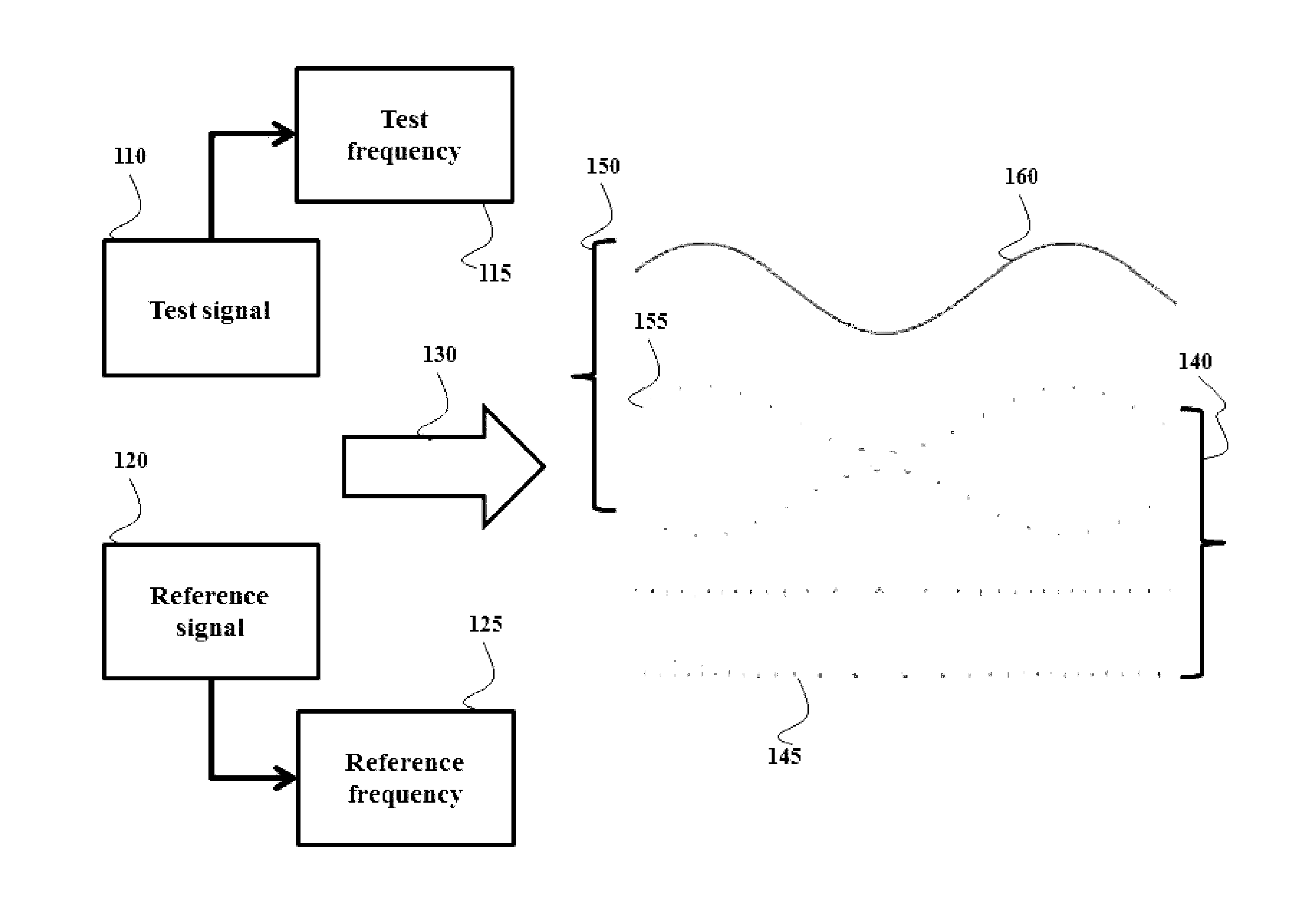
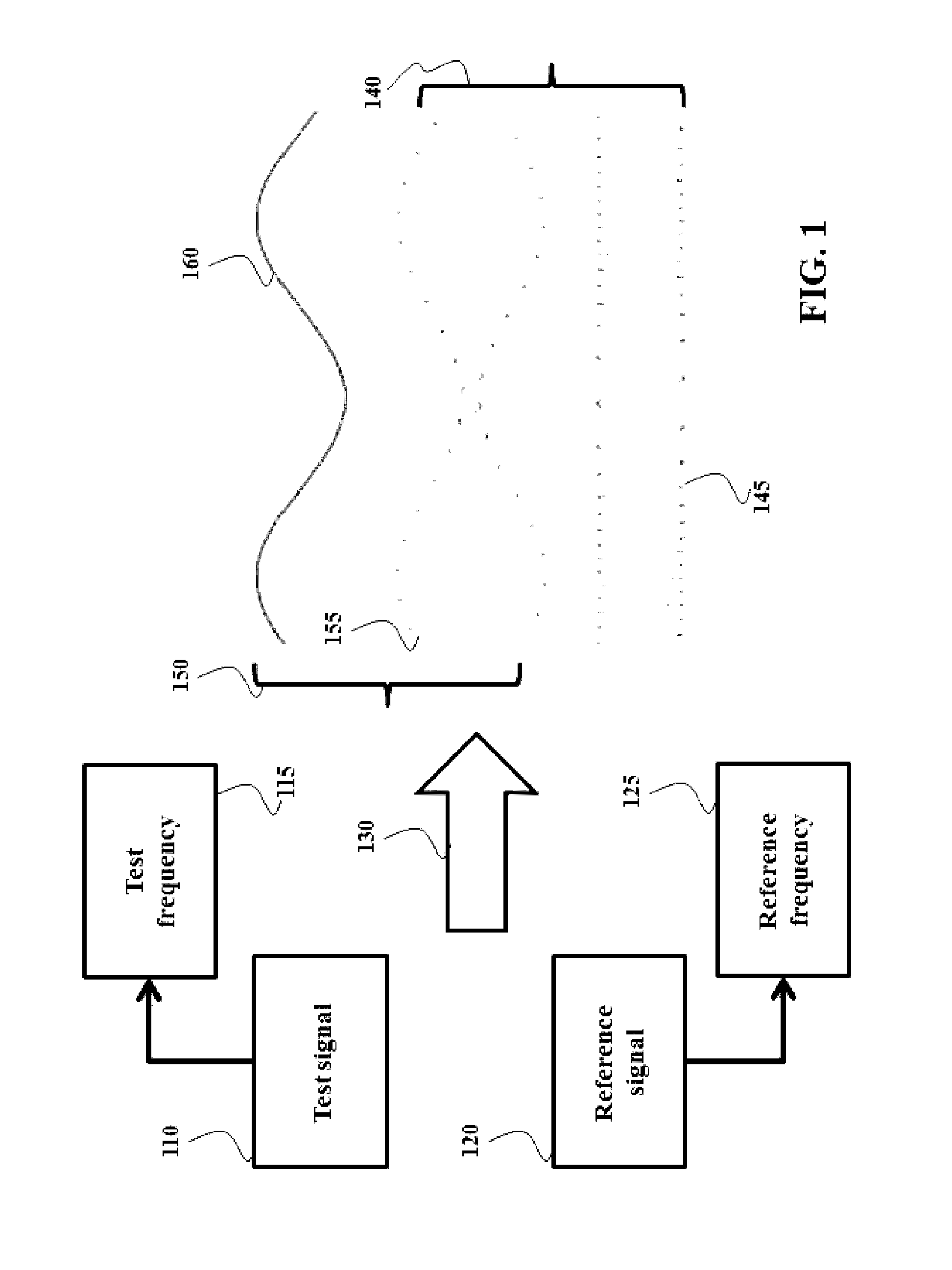
[0040]FIG. 1 shows an illustration of a realization employed by some embodiments of the invention to accurately measure high frequencies of the optical signals. If two signals, e.g., a test signal 110 and a reference signal 120 are added 130 to produce a third signal, the signal includes two components oscillating with frequencies depending on the value and differences between the frequencies of the mixed signals. For example, if the frequencies 115 and 125 of the signals 110 and 120 are randomly selected, the resulting signal 140 includes signals 155 and 145, which can be mixed together in an undistinguishable manner.

[0041]However, if two signals 110 and 1...


PUM


Abstract

A method determines a distance with a specified accuracy. The method transmits to an interferometer a test signal oscillating with a test frequency and receives, in response to the transmitting, an interferometric signal formed by interfering the test signal with a delayed signal produced by delaying a copy of the test signal over the distance equal to a path length difference in the interferometer. The test frequency is varying such that the test signal oscillates with different values of the test frequency. The method determines at least two values of the test frequency corresponding to particular values of the interferometric signal by beating the test signal with a reference signal having a reference frequency, wherein a value of the reference frequency is an absolute value predetermined with the specified accuracy. The method determines the distance using the two values of the test frequency.

Description

CROSS-REFERENCE TO RELATED APPLICATIONS[0001]This application claims the priority under 35 U.S.C. §119(e) from U.S. provisional application Ser. No. 61 / 740,670 filed on Dec. 21, 2012, the disclosure of which being incorporated herein by reference.FIELD OF THE INVENTION[0002]This invention relates to optical measurements of distances, and, in particular, to an optical system for interferometric measurement with specified accuracy.BACKGROUND OF THE INVENTION[0003]Laser interferometers are widely used to measure a distance. Laser interferometers operate by splitting radiation source into two beams, an object beam and a reference beam, using, for example, a beam splitter. The reference beam is directed to a reference mirror located at a known distance from the beam splitter. The object beam is directed to a surface of a target located at some unknown distance from the beam splitter. The object beam is reflected from the surface, and is recombined with the reference beam.[0004]The object...

Claims


Application Information

Patent Timeline
Patent Type & Authority Patents(United States)
IPC IPC(8): G01B9/02G01S7/48G01S17/32G01S7/491G01S7/4915G01S17/34
CPCG01B9/02003G01B9/02041G01S7/4808G01S7/4915G01S17/325G01S17/34
Inventor CHRISTENSEN, CALEB AZAVRIYEV, ANTONBEAL, A. CRAIG
Owner MAGIQ TECH INC
Why Eureka
Try Eureka