
Portable EV energy transfer apparatus and method

a technology of energy transfer apparatus and portability, applied in the field of electric vehicles, can solve the problems of imposing limitations on the manner in which energy can be transferred, requiring an extensive and complex network of control and monitoring modules, and unable to meet the requirements of the uiz system, so as to avoid esd

Active Publication Date: 2016-12-06
FORD GLOBAL TECH LLC
View PDF19 Cites 19 Cited by
  • Summary
  • Abstract
  • Description
  • Claims
  • Application Information

AI Technical Summary

Benefits of technology

The patent describes a method for coupling a portable EVETA to an EV and external load to transfer energy between them. This can include providing power to the external load in the form of AC or DC. The method includes performing an authorization process to protect against energy theft and monitoring the state of charge of the ESD to avoid overdischarge. The technical effects include improved efficiency and reliability in energy transfer and protection against unauthorized access.

Problems solved by technology

However, the Ruiz system requires an extensive and complex network of control and monitoring modules in addition to the electrical circuitry and equipment necessary to conduct the actual energy transfers between the vehicle, home grid and utility grid.
This feature can impose limitations on the manner in which energy can be transferred, such as a limitation that stored energy can be transferred from a vehicle battery only when the vehicle is tethered to a residential or commercial / industrial building.
When the appliances or electrical equipment to be powered reside at the building, this limitation may prove insignificant.
However, this type of system cannot be used in a situation in which an operator would like to use a vehicle's battery to power equipment that is not within the building, or is not connected to the home's electric grid.
In either case, since there is no building grid to tap into, the proposed systems cannot address the immediate need.

Method used


Image

  • Portable EV energy transfer apparatus and method
  • Portable EV energy transfer apparatus and method
  • Portable EV energy transfer apparatus and method

Examples


Embodiment Construction

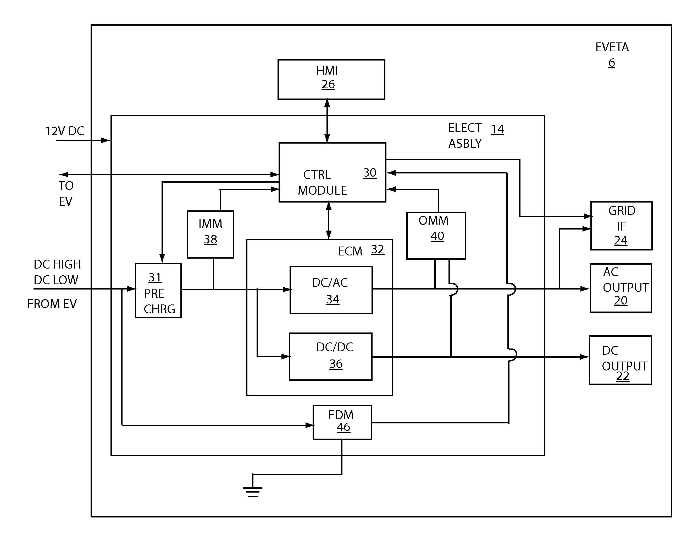
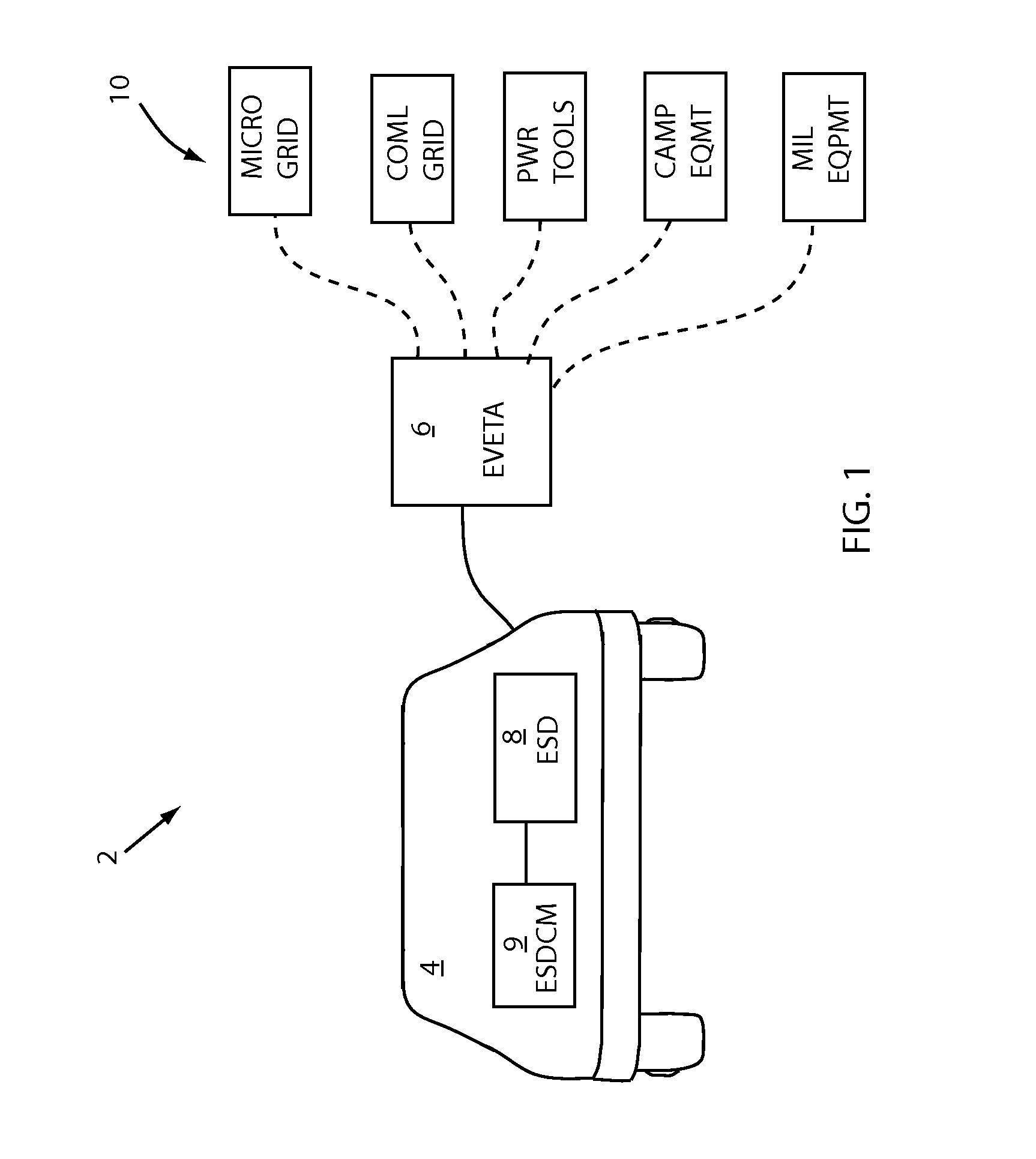
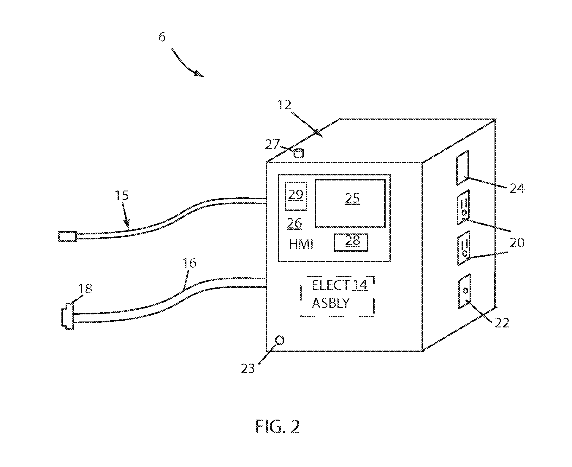
[0014]Example embodiments of the invention are presented herein; however, the invention may be embodied in a variety of alternative forms, as will be apparent to those skilled in the art. To facilitate understanding of the invention, and provide a basis for the claims, various figures are included in the specification. The figures are not drawn to scale and related elements may be omitted so as to emphasize the novel features of the invention. Structural and functional details depicted in the figures are provided for the purpose of teaching the practice of the invention to those skilled in the art, and are not to be interpreted as limitations. For example, control modules for various systems can be variously arranged and / or combined and may be omitted in illustrations of example embodiments herein in order to better emphasize novel aspects of the invention.

[0015]Turning now to the Drawings, in which like reference numerals refer to like elements throughout the several views, FIG. 1 ...


PUM


Abstract

Systems, apparatus, and methods are presented to transfer energy between an energy storage device (ESD) at an electrified vehicle (EV) and an AC or DC external load such as an electric grid, appliance or power tool. A portable EVETA can engage an EV charge inlet couple an EV, and can provide an AC outlet, a grid interface and a DC connector for coupling external loads. An EVETA can be used at a remote construction site or campsite to power high current equipment, obviating the need to transport an electric generator. An EVETA can be configured for data and control communication with the EV to coordinate energy transfer. An EVETA can receive a predetermined ESD state of charge limit so that the transfer process can be terminated to preserve sufficient charge for EV return to a desired destination. A human machine interface enables user input reception and information display.

Description

FIELD OF INVENTION[0001]This invention relates generally to electrified vehicles, and more particularly to transferring energy from a battery of an electrified vehicle to an external load.BACKGROUND OF INVENTION[0002]An electrified vehicle (EV) utilizes a high voltage traction battery or other type of energy storage device (ESD) to provide propulsion energy for an electric drive system. When the energy level is reduced or depleted, the battery can be charged by coupling the EV to a residential electric grid or to a public or commercial charging station. Fully charged, the battery can store energy for future driving operations. In the recent past, it has been suggested that the energy stored at an EV battery can be used for operations other than driving the vehicle. For example, it has been proposed that the battery of an electric vehicle be used to provide energy back to a residential electric grid. A vehicle-to-home (V2H) energy transfer process can reduce home utility costs as ene...

Claims


Application Information

Patent Timeline
Patent Type & Authority Patents(United States)
IPC IPC(8): H02J7/00B60L11/18
CPCB60L11/1842H02J7/0065H02J2007/0067Y02T90/168Y04S30/12Y02T90/16Y02T10/7072Y02T90/14Y04S10/126B60L1/006B60L53/16B60L55/00H02J2207/20Y02E60/00Y02T10/70H02J7/007182Y02T90/12Y02T90/167
Inventor LOFTUS, MICHAEL E.PROIETTY, JOHNSYED, FAZAL U.TABATOWSKI-BUSH, BEN A.MACNEILLE, PERRY R.
Owner FORD GLOBAL TECH LLC
Learn More