
High pressure gas container and manufacturing method for high pressure gas container

a gas container and high-pressure technology, applied in the direction of mechanical equipment, vessel construction details, other domestic articles, etc., can solve the problems of weak reinforcing fiber wound around the dome-shaped liner shoulder portion provided on the respective end portions of the liner, difficulty in ensuring mechanical strength in the liner shoulder portion, and time-consuming forming of the reinforcing layer

Inactive Publication Date: 2016-12-06
KYB CORP
View PDF12 Cites 2 Cited by
  • Summary
  • Abstract
  • Description
  • Claims
  • Application Information

AI Technical Summary

Benefits of technology

[0006]This invention has been designed in consideration of the problems described above, and an object thereof is to provide a high pressure gas container in which pressure resistance is secured, and a manufacturing method for the high pressure gas container with which mass production is possible.

Problems solved by technology

However, in a conventional high pressure gas container such as those disclosed in JP2006-300140A and JP2005-337391A, the reinforcing layer is formed by winding reinforcing fiber around the outer peripheral surface of the liner, and therefore reinforcing fiber wound around dome-shaped liner shoulder portions provided on respective end portions of the liner is weaker than reinforcing fiber wound around a liner trunk portion.
Hence, it is difficult to secure mechanical strength in the liner shoulder portions.
A process for forming the reinforcing layer is therefore time-consuming, making mass production difficult.

Method used


Image

  • High pressure gas container and manufacturing method for high pressure gas container
  • High pressure gas container and manufacturing method for high pressure gas container
  • High pressure gas container and manufacturing method for high pressure gas container

Examples


Embodiment Construction

[0013]An embodiment of this invention will be described below with reference to the figures.

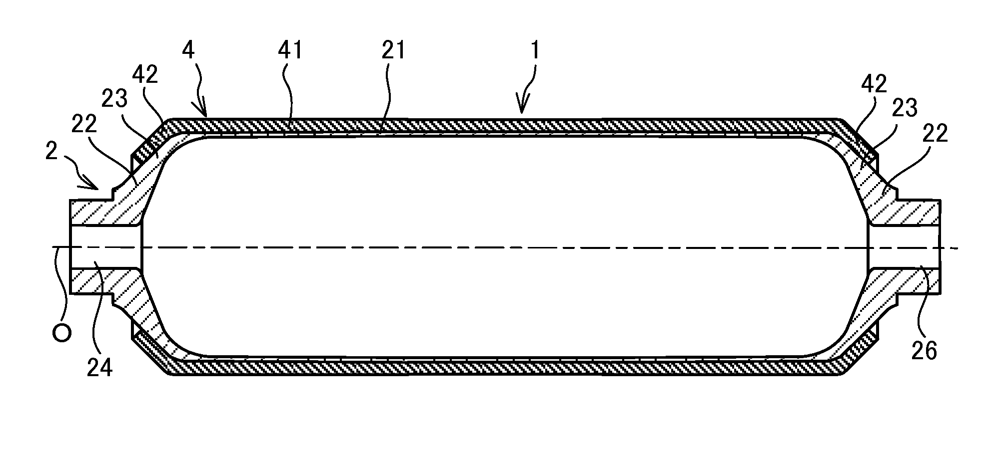
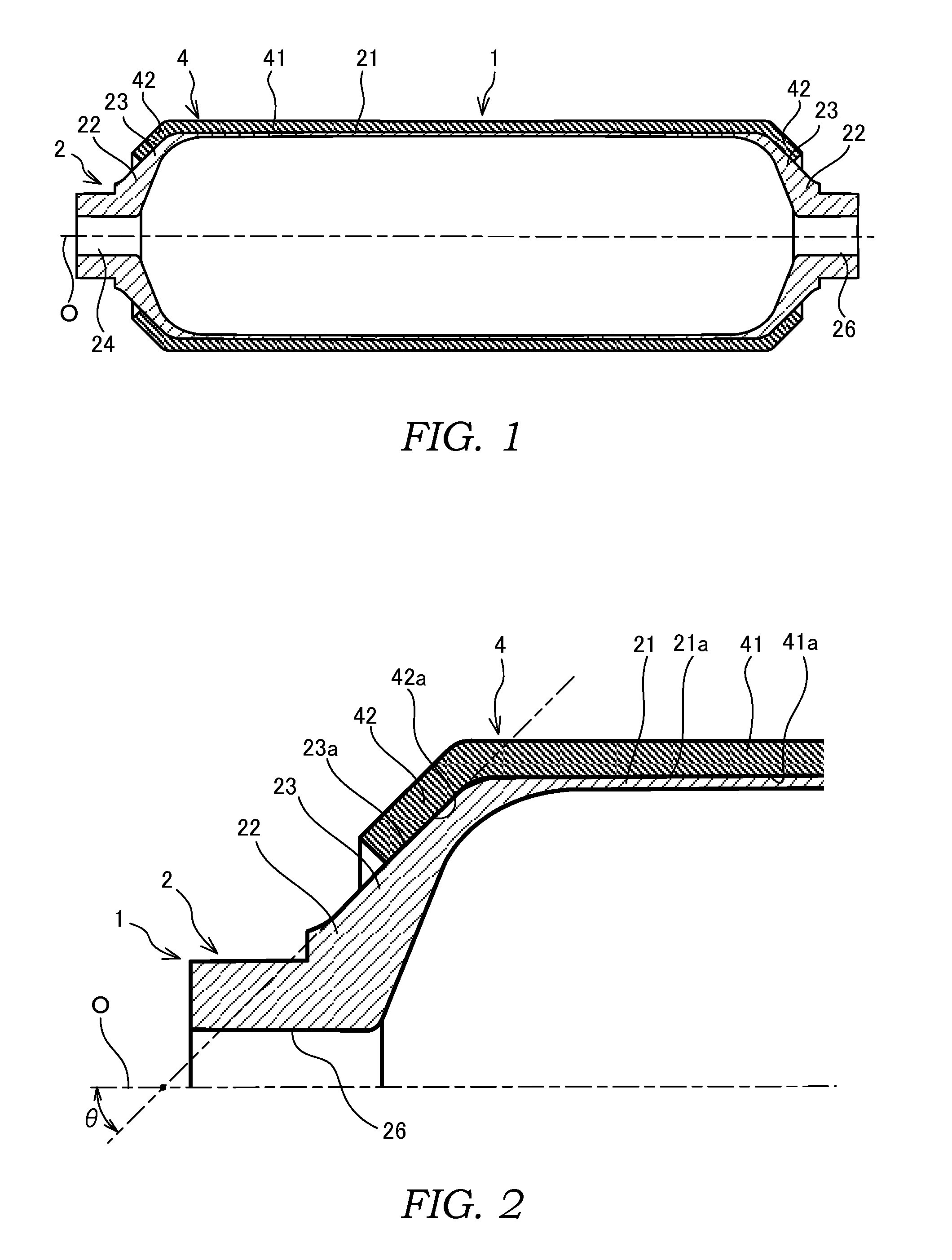
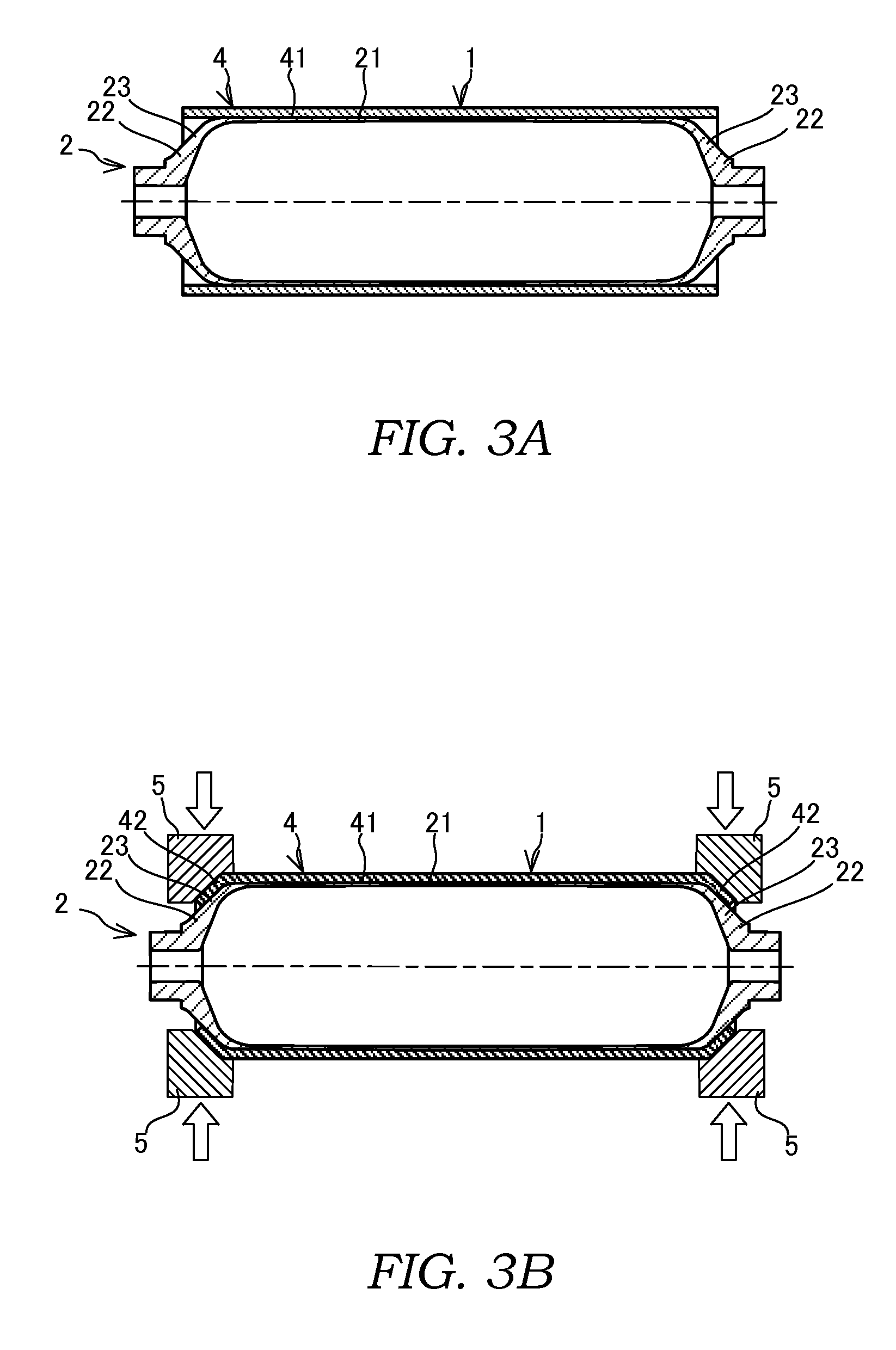
[0014]First, referring to FIGS. 1 and 2, a configuration of a high pressure gas container 1 according to this embodiment of this invention will be described. The high pressure gas container 1 is installed in a vehicle that uses hydrogen gas as a fuel, for example, in order to store high pressure hydrogen gas.

[0015]The hydrogen storage container 1 includes a liner 2 serving as a hollow main tank into which the high pressure hydrogen gas is charged, a hollow sub-tank, not shown in the figures, provided inside the liner 2, a hydrogen storage material housed inside the sub-tank, and a heat exchanger that cools and heats the hydrogen storage material. The high pressure gas container 1 is a hybrid type container including both the liner 2 and the sub-tank.

[0016]A powdered hydrogen storage alloy, for example, is used as the hydrogen storage material housed inside the sub-tank. The hydrogen storage a...


PUM

PropertyMeasurementUnit
pressureaaaaaaaaaa
diameteraaaaaaaaaa
incline angleaaaaaaaaaa

Abstract

This invention is a high pressure gas container into which a high pressure gas is charged, includes: a liner into which the high pressure gas is charged; and a reinforcing sleeve that envelops an outer surface of the liner, wherein the liner includes: a cylindrical liner trunk portion; and a pair of liner shoulder portions formed by reducing a diameter of respective end portions of the liner trunk portion, and the reinforcing sleeve includes: a sleeve trunk portion fitted to the liner trunk portion; and a pair of sleeve shoulder portions that extend from the sleeve trunk portion so as to contact the respective liner shoulder portions.

Description

RELATED APPLICATIONS[0001]The present application is National Phase of International Application Number PCT / JP2012 / 066714 filed Jun. 29, 2012 and claims priority to Japanese Application Number 2011-147550 filed Jul. 1, 2011.TECHNICAL FIELD[0002]This invention relates to a high pressure gas container filled with a high pressure gas, and a method of manufacturing the high pressure gas container.BACKGROUND ART[0003]A high pressure gas container having a tank-shaped liner filled with a high pressure gas is in use conventionally. For example, JP2006-300140A and JP2005-337391A propose high pressure gas containers in which a reinforcing layer is formed by fixing reinforcing fiber wound around an outer peripheral surface of the liner using resin in order to improve a pressure resistance, which constitutes a mechanical strength of the high pressure gas container.SUMMARY OF INVENTION[0004]However, in a conventional high pressure gas container such as those disclosed in JP2006-300140A and JP20...

Claims


Application Information

Patent Timeline
Patent Type & Authority Patents(United States)
IPC IPC(8): F17C1/02F17C1/04F17C1/06B21D51/24
CPCF17C1/04B21D51/24F17C1/06F17C2201/0109F17C2201/056F17C2203/0604F17C2203/0646F17C2203/0663F17C2221/012F17C2223/0123F17C2223/035F17C2223/036Y02E60/321Y02E60/32
Inventor NAKAMURA, YOSHINARIKOBAYASHI, TAKASHI
Owner KYB CORP
Learn More