Systems and methods for light amplification

a technology of light amplification and system, applied in the direction of active medium shape and construction, laser details, active medium materials, etc., can solve the problems of inability to achieve the desired effect of reducing the peak rate of heat deposition

Active Publication Date: 2016-12-06
MASSACHUSETTS INST OF TECH
View PDF6 Cites 3 Cited by
  • Summary
  • Abstract
  • Description
  • Claims
  • Application Information

AI Technical Summary

Benefits of technology

[0005]Embodiments of the present invention include apparatus, systems, and methods of optical amplification. In one example, a system for optical amplification includes a gain fiber with a core surrounded by a cladding. The core contains a gain medium characterized by a gain spectrum. The system also includes a seed light source and a control light source. The seed light source, in optical communication with the core, transmits seed light, at a first wavelength in the gain spectrum, into the core of the gain fiber where it is amplified. The seed light has a first linewidth greater than 100 MHz. The control light source, in optical communication with the core, transmits control light, at a second wavelength shorter than the first wavelength, into the core where it interacts with the pumped gain medium so as to reduce the peak rate of heat deposition per unit length along the fiber and mitigate multimode instability of the amplified seed light. The control light has a second linewidth greater than 100 MHz. The system further includes a pump source, in optical communication with the gain fiber, to transmit pump light at a pump wavelength, shorter than the second wavelength, into the gain fiber so as to pump the gain medium and amplify the seed light.
[0006]In another example, a method of optical amplification includes propagating seed light at a first wavelength in a core of a gain fiber. The core of the gain fiber includes a gain medium to amplify the seed light. The seed light has a first linewidth greater than 100 MHz. The method also includes propagating control light at a second wavelength, shorter than the first wavelength, in the core of the gain fiber where it interacts with the pumped gain medium so as to reduce the peak rate of heat deposition per unit length along the fiber and mitigate multimode instability of the amplified seed light. The control light has a second linewidth greater than 100 MHz. The method further includes coupling pump light, at a third wavelength shorter than the second wavelength, into the gain fiber so as to pump the gain medium and amplify the seed light.
[0007]In yet another example, an optical amplifier includes a large-mode-area (LMA) gain fiber containing a Yb-doped gain medium, a seed light source, a control light source, and a pump light source. The seed light source, in optical communication with the LMA gain fiber, transmits seed light, at a first wavelength in the range from about 1040 nm to about 1080 nm, into a core of the LMA gain fiber where it is amplified. The seed light has a first linewidth greater than 100 MHz. The control light source, in optical communication with the LMA gain fiber, transmits control light, at a second wavelength in the range from about 1025 nm to about 1045 nm, into the core of the LMA gain fiber where it interacts with the pumped gain medium so as to reduce the peak rate of heat deposition per unit length along the fiber and mitigate multimode instability of the seed light. The control light has a second linewidth greater than 100 MHz. The pump source, in optical communication with the LMA gain fiber, transmits pump light, at a pump wavelength in the range from about 900 nm to about 985 nm, into the LMA gain fiber so as to pump the gain medium and amplify the seed light.

Problems solved by technology

These techniques may breakdown when LMA fiber amplifiers are operated at high power.
Specifically, the useful output power or energy from LMA fiber amplifiers can be limited by multimode instability (MMI), also referred to as transverse-mode instability (TMI) and sometimes just mode instability (MI), which couples power (energy) between the fundamental and higher-order transverse modes of the LMA fiber.

Method used


Image

  • Systems and methods for light amplification
  • Systems and methods for light amplification
  • Systems and methods for light amplification

Examples


Embodiment Construction

[0024]Overview

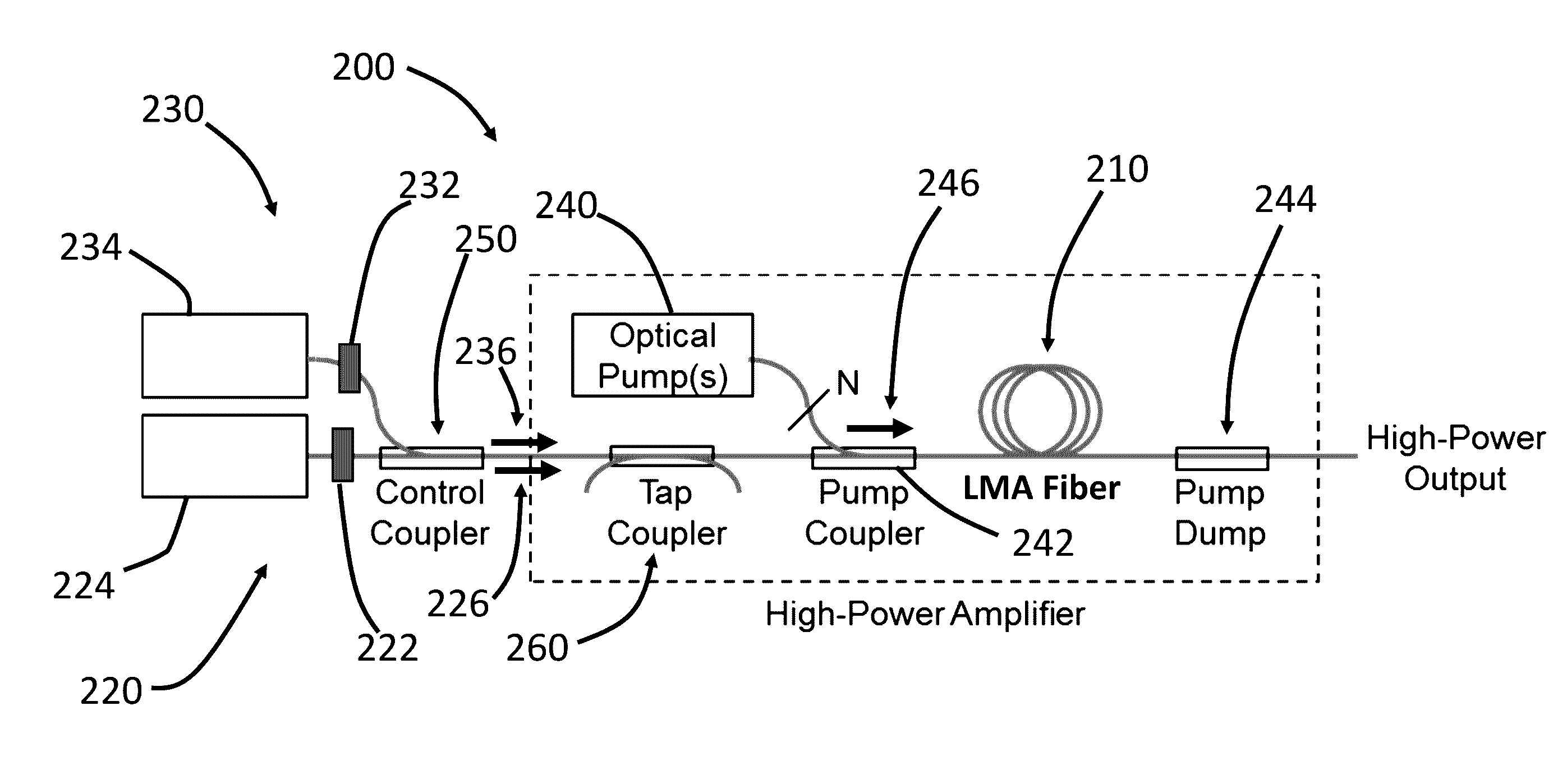
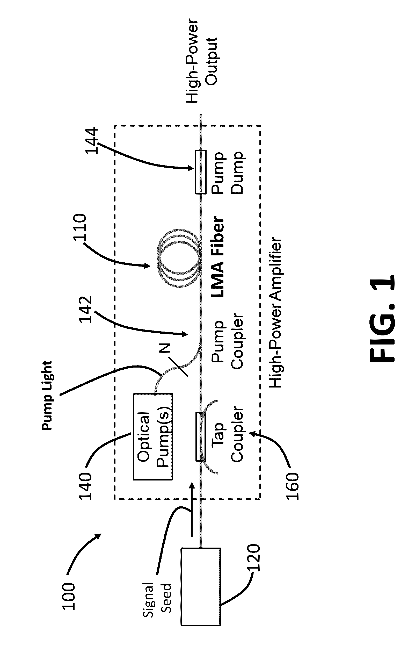
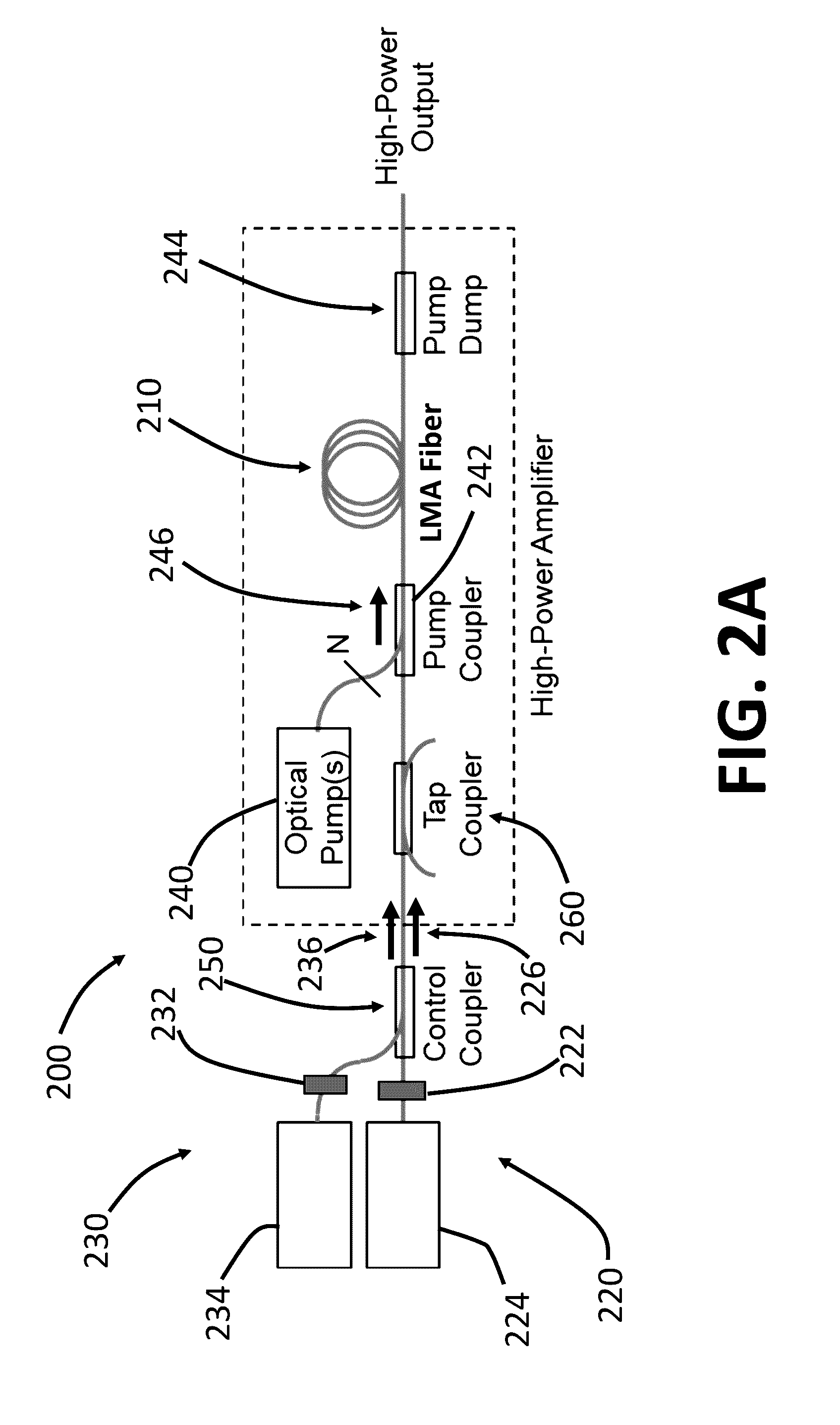
[0025]FIG. 1 shows a typical optical system 100 of a high-power Yb-doped large-mode-area (LMA) fiber amplifier. The system 100 includes a LMA gain fiber 110 within which a signal seed, provided by a signal seed source 120, is amplified. The LMA gain fiber 110 is pumped by a pump source 140 via a pump coupler 142. A pump dump 144 is disposed after the LMA gain fiber 110 to collect pump light that is not absorbed in the LMA fiber 110. A tap coupler 160 is disposed between the signal seed source 120 and the LMA gain fiber 110 to couple out a portion of the seed signal or feedback from the LMA gain fiber 110 for monitoring.

[0026]One issue with conventional LMA fiber amplifiers (e.g., the system 100 shown in FIG. 1) is that LMA fibers normally support not only the fundamental mode (i.e., LP01 mode) of the light being amplified, but also higher-order modes. The presence of higher-order modes can induce multimode instability (MMI), which can limit the useful output power or e...


PUM


Abstract

A system for optical amplification includes an optical fiber with a core containing a gain medium surrounded by a cladding, a seed light source, a control light source, and a pump source. The seed light source transmits seed light, at a first wavelength and having a first linewidth greater than 100 MHz, into the core of the fiber. The control light source transmits control light, at a second wavelength shorter than the first wavelength, into the core where it interacts with the pumped gain medium so as to reduce the peak rate of heat deposition per unit length along the fiber. The control light has a second linewidth greater than 100 MHz. The pump source transmits pump light at a pump wavelength, shorter than the second wavelength, into the fiber so as to pump the gain medium and amplify the seed light.

Description

CROSS-REFERENCE TO RELATED APPLICATIONS[0001]This application claims priority to U.S. provisional application Ser. No. 62 / 109,155, filed Jan. 29, 2015, entitled “TECHNIQUE FOR MITIGATING MULTIMODE INSTABILITIES IN HIGH-POWER LARGE-MODE-AREA FIBER AMPLIFIERS,” which is hereby incorporated herein by reference in its entirety.GOVERNMENT SUPPORT[0002]This invention was made with Government support under Contract No. FA8721-05-C-0002 awarded by the U.S. Air Force. The Government has certain rights in the invention.BACKGROUND[0003]The useful output power P or energy E (E=Pτ, τ is the duration of the optical pulse in a pulsed system) from fiber amplifiers can be limited by nonlinear optical interactions in the fiber, such as self-phase modulation (SPM), cross-phase modulation (XPM), four-wave mixing (FWM), stimulated Raman scattering (SRS), and stimulated Brillouin scattering (SBS). These nonlinear interactions become detrimental when the intensity I (I=P / A, A is the effective cross-sectio...

Claims


Application Information

Patent Timeline
Patent Type & Authority Patents(United States)
IPC IPC(8): H01S3/067H01S3/094H01S3/16H01S3/00H01S3/08
CPCH01S3/0804H01S3/0085H01S3/06733H01S3/06754H01S3/06762H01S3/094003H01S3/1618H01S3/094007H01S3/10015H01S3/1003
Inventor ZAYHOWSKI, JOHN J.MARTZ, DALE H.
Owner MASSACHUSETTS INST OF TECH
Why Eureka
Try Eureka