Vehicle control apparatus

a technology for controlling apparatus and vehicles, applied in the direction of vehicular safety arrangements, pedestrian/occupant safety arrangements, instruments, etc., can solve the problems of improper timing of alarms and unconsidered vehicle situations

Active Publication Date: 2016-12-27
TOYOTA JIDOSHA KK +1
View PDF13 Cites 52 Cited by
  • Summary
  • Abstract
  • Description
  • Claims
  • Application Information

AI Technical Summary

Benefits of technology

[0010]In the above-described vehicle control apparatus according to the first aspect of the disclosure, the control unit may be configured to execute an extension control of the departure margin time by at least one of deceleration of the vehicle and restriction of the steering control range, in a case where the difference resulting from subtracting the driving return time from the departure margin time is a second threshold or less. Since the vehicle control apparatus executes the extension control of the departure margin time in the case where the difference resulting from subtracting the driving return time from the departure margin time is the second threshold or less, it is possible to secure the time for the driver to return to the driving operation before the vehicle departs from the running lane, even when an abnormality such as a false recognition occurs in the apparatus while the driver continues the hand-release state for example.

Problems solved by technology

However, in the above-described related apparatus, the situation of the vehicle is not considered.
Therefore, there is a possibility that the alarm is performed at an improper timing that is not appropriate to the situation of the vehicle.

Method used


Image

  • Vehicle control apparatus
  • Vehicle control apparatus
  • Vehicle control apparatus

Examples


first embodiment

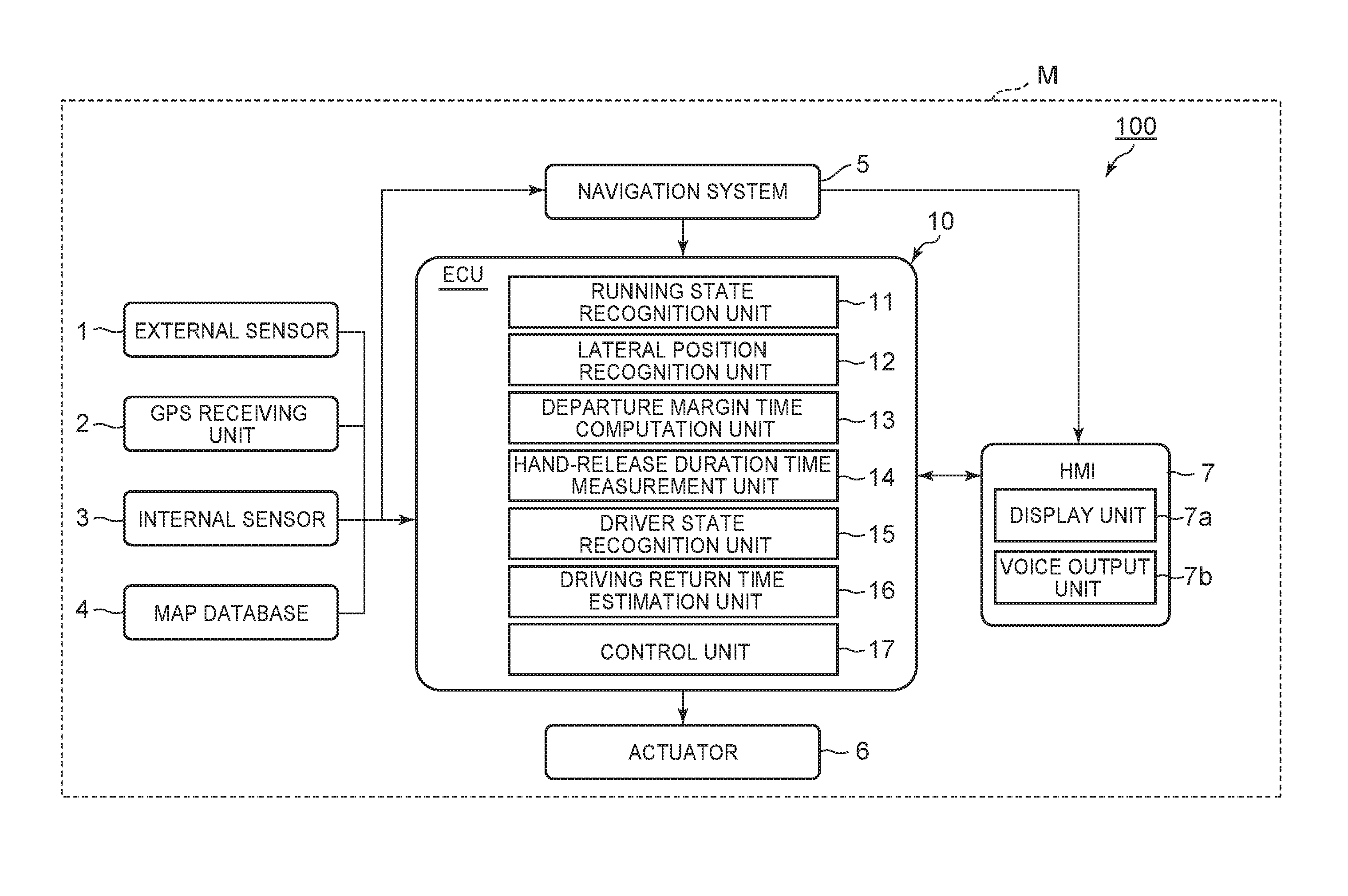
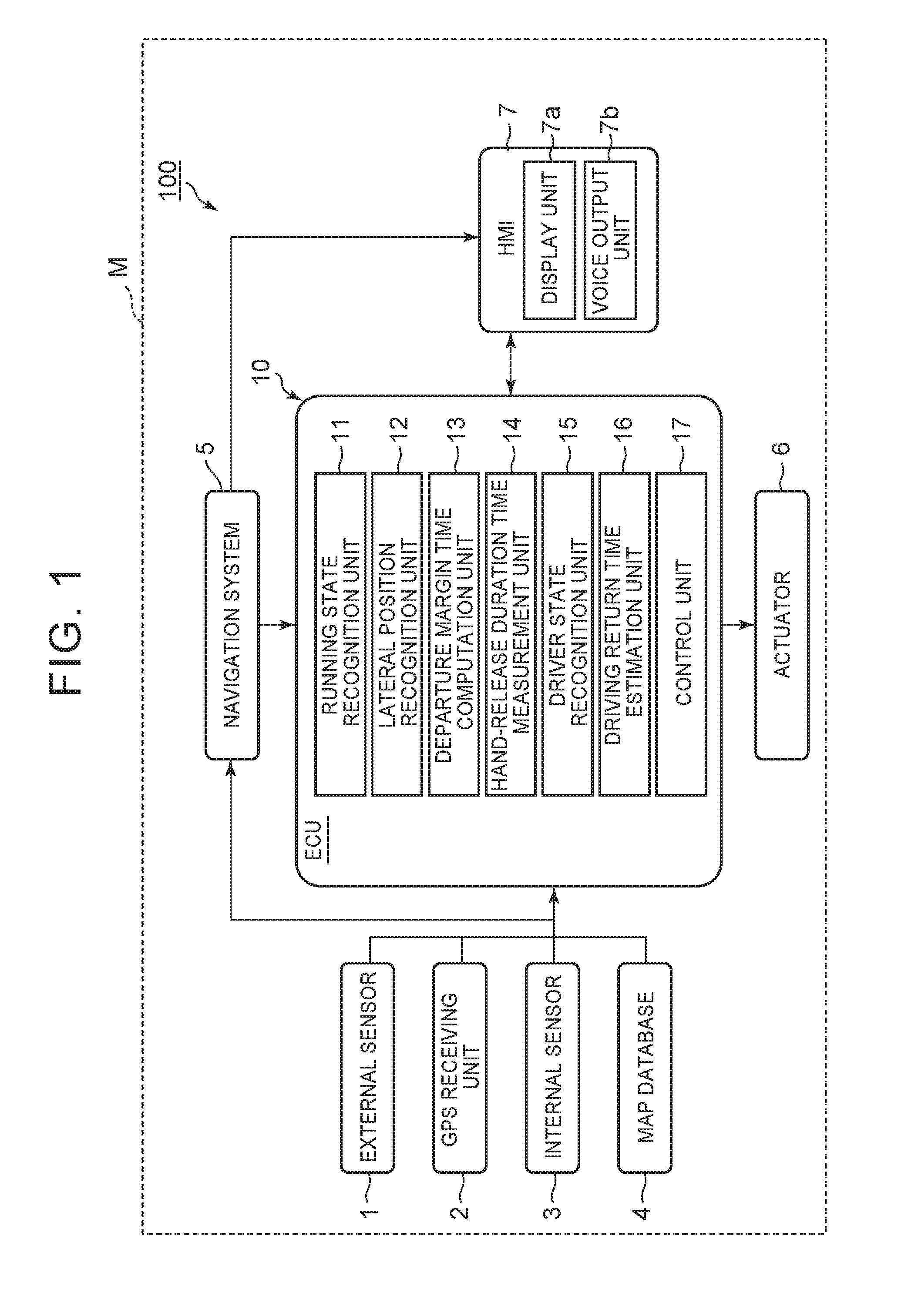
[0041]In the following, a configuration of the vehicle control apparatus 100 will be described with reference to FIG. 1. As shown in FIG. 1, the vehicle control apparatus 100 includes an external sensor 1, a GPS [Global Positioning System] receiving unit 2, an internal sensor 3, a map database 4, a navigation system 5, an actuator 6, an HMI [Human Machine Interface]7, and an ECU [Electronic Control Unit]10.

[0042]The external sensor 1 is detection equipment to detect the external situation that is the surrounding information of the vehicle M. The external sensor 1 includes at least a camera. The camera, for example, is provided on the back side of a windshield of the vehicle M. The camera sends the imaging information relevant to the external situation of the vehicle M, to the ECU 10. The camera may be a monocular camera, or may be a stereo camera. The stereo camera includes two imaging units (e.g., at least two cameras) arranged such that binocular parallax is reproduced.

[0043]The ...

second embodiment

[0118]As shown in FIG. 8, in step S201, the ECU 20 of the vehicle control apparatus 101 determines whether there is an obstacle around the vehicle M by the obstacle information acquisition unit 21. The obstacle information acquisition unit 21, for example, determines whether there is an obstacle around the vehicle M, based on the obstacle information acquired from the radar. In the case of determining that there is no obstacle around the vehicle M (S201: NO), the ECU 20 finishes the process this time. Thereafter, the process is repeated again from step S201, after the elapse of a previously set time. In the case of determining that there is an obstacle around the vehicle M (S201: YES), the ECU 20 transitions to step S202.

[0119]In step S202, the ECU 20 performs the computation of the contact margin time by the contact margin time computation unit 22. The contact margin time computation unit 22 computes the contact margin time, which is the time (for example, the minimum time) until ...


PUM


Abstract

A vehicle control apparatus includes a departure margin time computation unit configured to compute a departure margin time until the vehicle departs from the running lane in a previously set steering control range and vehicle speed control range, a hand-release duration time measurement unit configured to measure a hand-release duration time, a driving return time estimation unit configured to estimate a driving return time until the driver in the hand-release state returns to driving operation, based on the hand-release duration time, and a control unit configured to output an alarm to the driver when a difference resulting from subtracting the driving return time from the departure margin time is a first threshold or less.

Description

CROSS REFERENCE TO RELATED APPLICATIONS[0001]This application claims priority from Japanese Patent Application No. 2015-075170 filed on Apr. 1, 2015, the disclosure of which including the specification, drawings and abstract is incorporated herein by reference in its entirety.BACKGROUND[0002]1. Field[0003]This disclosure relates to a vehicle control apparatus that controls a vehicle such that the vehicle runs along a running lane.[0004]2. Description of Related Art[0005]In a vehicle control apparatus that controls a vehicle such that the vehicle runs along a running lane, the vehicle runs without requiring the driving operation, and therefore, a driver is sometimes in a hand-release state in which the driver has released his hands from a steering wheel. As for such a hand-release state, Japanese Patent Application Publication No. 7-25301 describes an apparatus that raises an alarm in the case where the driver continues the hand-release state for a given time or more.[0006]However, i...

Claims


Application Information

Patent Timeline
Patent Type & Authority Patents(United States)
IPC IPC(8): B60Q9/00B60W10/04B60W40/08B60W10/20
CPCB60Q9/00B60W10/04B60W10/20B60W40/08B60W2040/0827B60W2540/26B60W2710/20B60W2710/30B60W2720/10B60W30/12B60W50/14B60W2540/18B60W2540/12B60W2540/10B60W2520/28B60W2520/125B60W2520/105B60W2050/146B60W2050/143B60W2554/00B60W2556/50B60W30/16B60W30/0953B60W30/0956G08G1/167G08B21/06G06V20/597G06V20/588B60W40/02B60R21/015B62D6/00B60W30/08B60W2540/225B60W2554/4029B60W2554/4026B60W2554/20B60W2540/223B60W2540/229B60W2554/80B60W2540/221
Inventor MATSUMURA, TAKESHI
Owner TOYOTA JIDOSHA KK
Why Eureka
Try Eureka