Radio receiver and electronic timepiece

a radio receiver and electronic timepiece technology, applied in the direction of radio-controlled timepieces, instruments, measurement devices, etc., can solve the problems of consuming power in excess, affecting the power consumption of the entire electronic timepiece, and consuming power by the rf circui

Active Publication Date: 2016-12-27
CASIO COMPUTER CO LTD
View PDF10 Cites 4 Cited by
  • Summary
  • Abstract
  • Description
  • Claims
  • Application Information

AI Technical Summary

Benefits of technology

[0007]To achieve the aforementioned object, an aspect of the present invention is a radio receiver including: a signal amplification unit configured to receive a radio wave transmitted from a positioning satellite and amplify a signal of the received transmitted radio wave; an acquisition unit to which the signal amplified by the signal amplification unit is input, the acquisition unit being configured to acquire a satellite signal containing position information and date and time information from the signal; and a control unit configured to obtain at least one of the position information and the date and time information from the satellite signal acquired by the acquisition unit, determine a reception condition of the transmitted radio wave based on at least one of a processing condition of the obtainment and a processing condition of the acquisition unit, and perform operation setting of a gain of the signal amplification unit according to the determined reception condition, wherein the control unit performs the operation setting so that the gain set in the operation setting when the reception condition is determined to be a first reception condition is smaller than the gain set in the operation setting when the reception condition is determined to be a second reception condition inferior to the first reception condition.

Problems solved by technology

As a result, power consumed by the RF circuits has a significant influence on the power consumption of the entire electronic timepiece.
Hence uniform reception operation where the reception conditions are not considered may disadvantageously consume power in excess.

Method used


Image

  • Radio receiver and electronic timepiece
  • Radio receiver and electronic timepiece
  • Radio receiver and electronic timepiece

Examples


first embodiment

[0016][First Embodiment]

[0017]A first embodiment of the present invention will be described below with reference to the drawings.

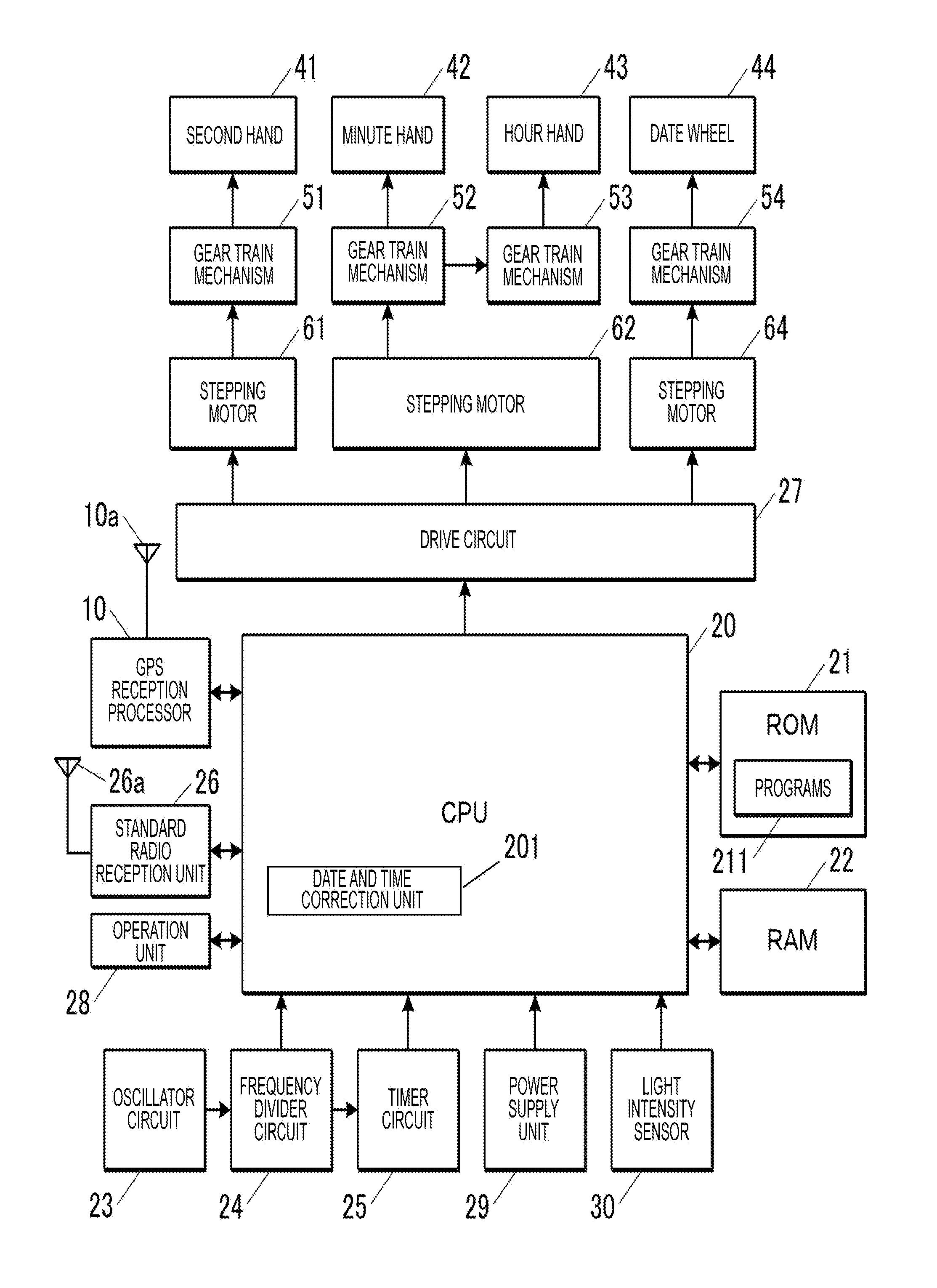
[0018]FIG. 1 is a block diagram illustrating a functional configuration of an electronic timepiece 1 according to the first embodiment of a radio receiver and electronic timepiece of the present invention.

[0019]The electronic timepiece 1 is an analog electronic timepiece for displaying date and time using hands, but is not particularly limited thereto. The electronic timepiece 1 includes a control unit 20 (central processing unit) (date and time correction unit 201), a read only memory (ROM) 21, a random access memory (RAM) 22, an oscillator circuit 23, a frequency divider circuit 24, a timer circuit 25 (timer unit), a GPS reception processor 10 and an antenna 10a thereof, a standard radio reception unit 26 and an antenna 26a thereof, a drive circuit 27, an operation unit 28, a power supply unit 29, a light intensity sensor 30, a second hand 41 and a gear ...

second embodiment

[0102][Second Embodiment]

[0103]Next, a second embodiment of the present invention will be described. The configuration of an electronic timepiece 1 according to the second embodiment is the same as that in the first embodiment. The second embodiment is different from the first embodiment in that the electronic timepiece 1 obtains date and time information by using transmitted radio waves from GPS satellites (date and time obtaining process) and that the date and time counted by the timer circuit 25 is corrected based on the obtained date and time information (date and time correction process). Hereinafter, differences from the first embodiment will be mainly described.

[0104]The date and time correction process performed in the second embodiment is started at a predetermined frequency such as at predetermined time once a day or when the light intensity measured by the light intensity sensor 30 has reached a predetermined reference level or higher for the first time in a day. For the ...

third embodiment

[0123][Third Embodiment]

[0124]Next, a third embodiment of the present invention will be described. The configuration of an electronic timepiece 1 according to the third embodiment is the same as that in the first and second embodiments. In the third embodiment, determination of the reception condition based on the signal-to-noise ratios (SNRs) of demodulated signals containing acquired satellite signals is also performed in the operation of obtaining a local time in the first embodiment. In the present embodiment, the control unit 123 also functions as a signal-to-noise ratio calculation unit. Hereinafter, differences from the first embodiment will be mainly described.

[0125]FIGS. 8 and 9 are flowcharts illustrating control procedures performed by the control unit 123 in the local time obtaining process performed by the GPS reception processor 10. The local time obtaining process according to this modification corresponds the local time obtaining process of the first embodiment illus...


PUM


Abstract

A radio receiver receives transmitted radio waves from positioning satellites, and includes: a signal amplification unit configured to amplify a received signal; an acquisition unit configured to acquire a satellite signal from the amplified signal; and a control unit configured to obtain predetermined information from the acquired satellite signal, determine a reception condition of transmitted radio waves based on the processing condition of at least one of the obtainment and the acquisition unit, and performs operation setting of a gain of the signal amplification unit according to the determined reception condition, wherein the control unit performs the operation setting so that the gain set in the operation setting when the reception condition is determined to be a first reception condition is smaller than the gain set in the operation setting when the reception condition is determined to be a second reception condition inferior to the first reception condition.

Description

BACKGROUND OF THE INVENTION[0001]This invention relates to a radio receiver and an electronic timepiece that receive radio waves transmitted from positioning satellites.[0002]In related art, there are electronic timepieces that receive radio waves transmitted from positioning satellites of a global navigation satellite system (GNSS) to obtain date and time and a position. Such an electronic timepiece amplifies, converts the frequencies of, and filters the received radio waves by RF (radio frequency) circuits, and demodulates and decodes the radio waves in a demodulated signal process to obtain necessary information.[0003]In reception of radio waves transmitted from positioning satellites, there are specific circumstances in which satellite signals of transmitted radio waves that can be received need to be quickly searched for and acquired from radio waves transmitted from multiple positioning satellites and in which these acquired satellite signals need to be obtained in parallel. A...

Claims


Application Information

Patent Timeline
Patent Type & Authority Patents(United States)
IPC IPC(8): G04R20/04G01S19/14G01S19/34G01S19/36G01S19/28
CPCG04R20/04G01S19/34G01S19/36G01S19/14G01S19/28
Inventor MATSUE, TAKESHI
Owner CASIO COMPUTER CO LTD
Why Eureka
Try Eureka