Device and method for decontamination, disinfection, and sanitation

a technology of decontamination and disinfection, applied in the direction of disinfection, life-saving devices, chemicals, etc., can solve the problems of flash vaporization, severe scaling limitations, and ineffective production of large quantities of vapors

Active Publication Date: 2017-01-03
NANOMIST SYST
View PDF6 Cites 5 Cited by
  • Summary
  • Abstract
  • Description
  • Claims
  • Application Information

AI Technical Summary

Benefits of technology

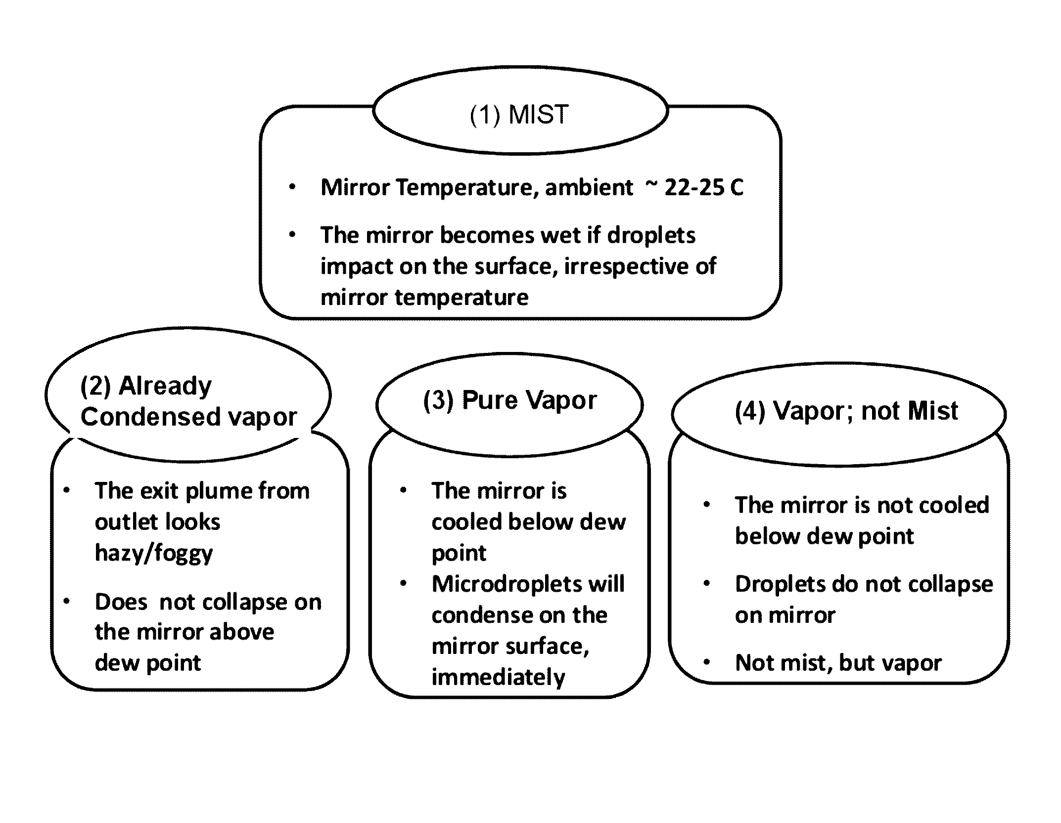
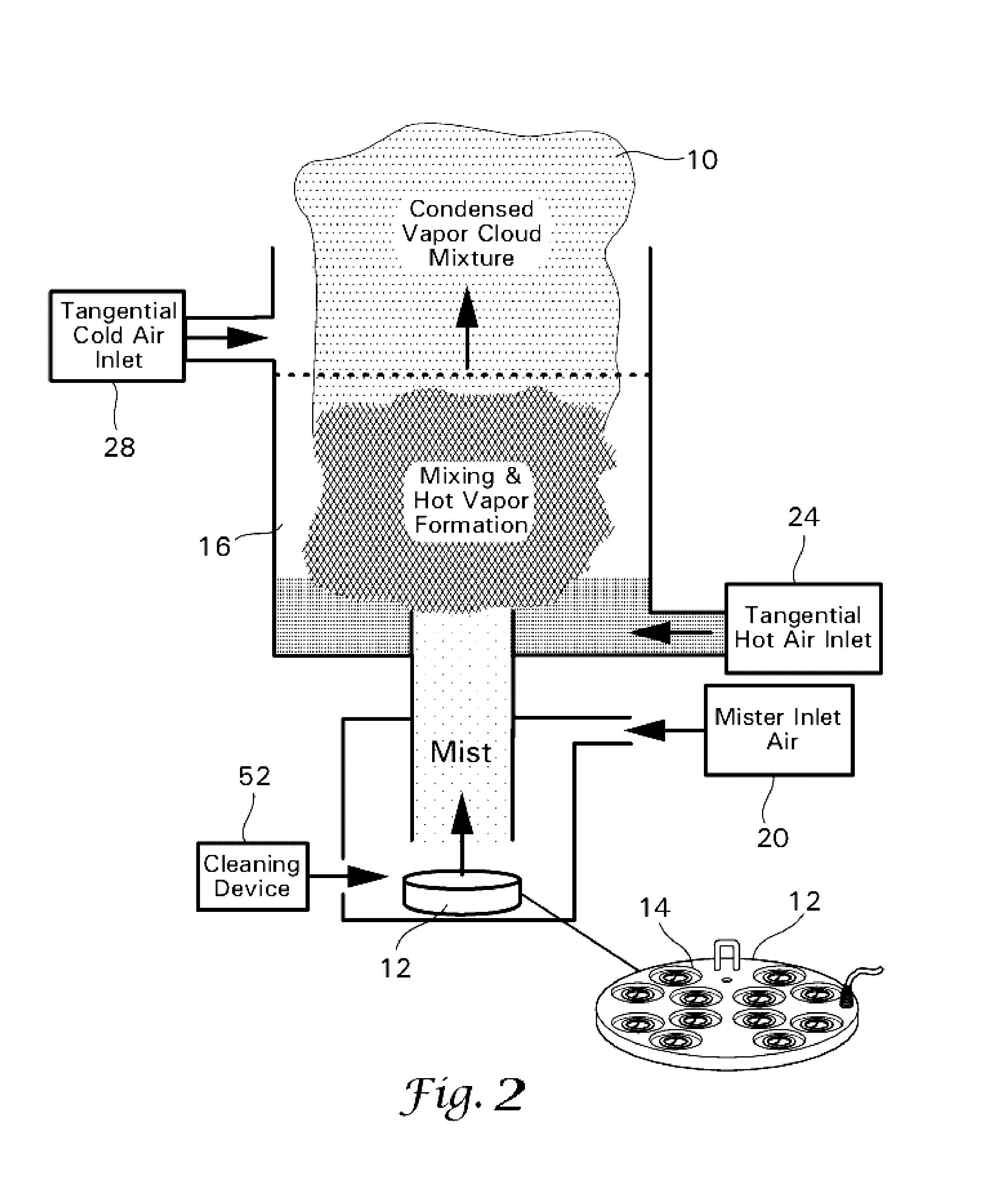
[0021]Accordingly, the overall objective of this invention is to provide a method and device for efficiently premixing warm air and ultrafine biocide mist to form a condensed vapor cloud which is then dispersed into a volume. The warm air and ultrafine biocide are instantaneously evaporated and produce a large quantity of low temperature vapors from ultra-fine mist of single or multicomponent biocide or other liquids without heating them to their boiling points. Using high humidity combined with a reasonably elevated temperature, relative to the environment of the volume where dispersed, vapor is produced inside an evaporator tube / drying tube / device and when it is mixed with cooler air, such as when it is discharged into the environment of the volume to be decontaminated, it forms a condensed vapor cloud. According to this invention a condensed vapor cloud of the biocide is dispersed into the volume to be decontaminated. Depending on the room temperature and room air humidity, the condensed vapor cloud discharged may “re-evaporate” and become vapor or may remain condensed vapor (liquid droplets) or may partially evaporate creating a mixture of vapor and condensed vapor. Further, the condensed vapor cloud discharged will contain a much higher concentration of the biocide within the liquid solution in each droplet than the original low concentration biocide because the high boiling point (high vapor pressure) liquid component concentrates in the condensed phase. The process parameters can be varied, including initial room temperature and humidity, to manipulate the condensed vapor cloud such that it may later become pure vapor, condensed vapor, or some mixture thereof. In one embodiment, a secondary cooler air inlet may be installed downstream of the vapor zone inside the tube, prior to its exit into the room. This cool air will enhance the condensed vapor formation within the tube and at the exit via lower dew point.
[0022]It is another objective of this invention to avoid detrimental thermal impact to the chemistry of the input components by avoiding excessive heat in the evaporation process, as encountered in the hot plate flash vaporization process.
[0023]It is another objective to use nearly “monodisperse” ultrafine mist droplets of multicomponent liquids that are produced from a source such as an ultrasonic atomization device so that the mist-to-vapor conversion rate is very high and efficient.
[0025]It is another objective to vary the configuration of the vapor discharge port or ports to facilitate high dispersion efficiency of the condensed vapor cloud formed upon discharge.
[0027]It is a further objective to generate a general principle for combining mist and hot air streams to facilitate efficient mixing and evaporation such that those who are skilled in the art may devise designs that incorporate co-flows, opposing flows, and shearing flows with widely varying flow angles.

Problems solved by technology

For example, the vapors are produced above the boiling point and exit with elevated temperatures, the flash vaporization by hot plate and heated blocks is proven to be inefficient in producing large quantity of vapors due to the small surface area per unit of mass of large liquid pools, films, or droplets for heat and mass transfer, and there are severe scaling limitations because of the large-scale heating structures needed to vaporize scalable amount of liquids and thermal inertia problems.
The prior art does not teach a methodology of using hydrogen peroxide as a sterilizing agent that would be applicable to the need for an improved method of discharging a condensed vapor or condensed vapor mixture of hydrogen peroxide into the volume to be decontaminated where a concentrated biocide solution might be preferred.
This renders the system costly and not scalable for large scale vapor production for commercial applications.
This pressure, and the sudden release of this high pressure at the nozzle orifice, can have detrimental effects on various chemical components of biocides to be vaporized and may pose safety concerns.
Further, spray nozzles are subject to erosion, clogging and other such problems that can cause inconsistencies in the output droplet sizes which, as is clearly shown above, will have tremendous detrimental impact on the vaporization process.
The prior art does not teach a methodology of using hydrogen peroxide as a sterilizing agent that would be applicable to the need for an improved method of creating a monodisperse mist to provide efficient, complete evaporation of a solution in order to subsequently discharge a condensed vapor or condensed vapor mixture of hydrogen peroxide into the volume to be decontaminated where a concentrated biocide solution might be preferred.
Because the heating of the mist does not occur until the two streams reach the environment outside of the device, the enthalpy associated with the hot air stream dissipates into the environment decreasing the efficiency of the evaporation process considerably.
While forced convection helps the rate via enhanced heat and mass transfer across the surface, this alone does not guarantee the droplet entrainment into the air, mixing by turbulence and subsequent heat and mass transfer processes.
Beyond these, the limiting factor is the number density of droplets that controls the local humidity around individual droplets.

Method used


Image

  • Device and method for decontamination, disinfection, and sanitation
  • Device and method for decontamination, disinfection, and sanitation
  • Device and method for decontamination, disinfection, and sanitation

Examples


Embodiment Construction

[0049]The following description is intended to provide the reader with a better understanding of the invention. The description is not intended to be limiting with respect to any element not otherwise limited within the claims.

[0050]The present invention discloses a short length evaporation process that focuses on the resultant vapor as a means of producing a desired and optimized output in the form of a condensed vapor cloud discharged into an environment to be decontaminated, preferably a room or an enclosed volume for decontamination, disinfection or sanitation.

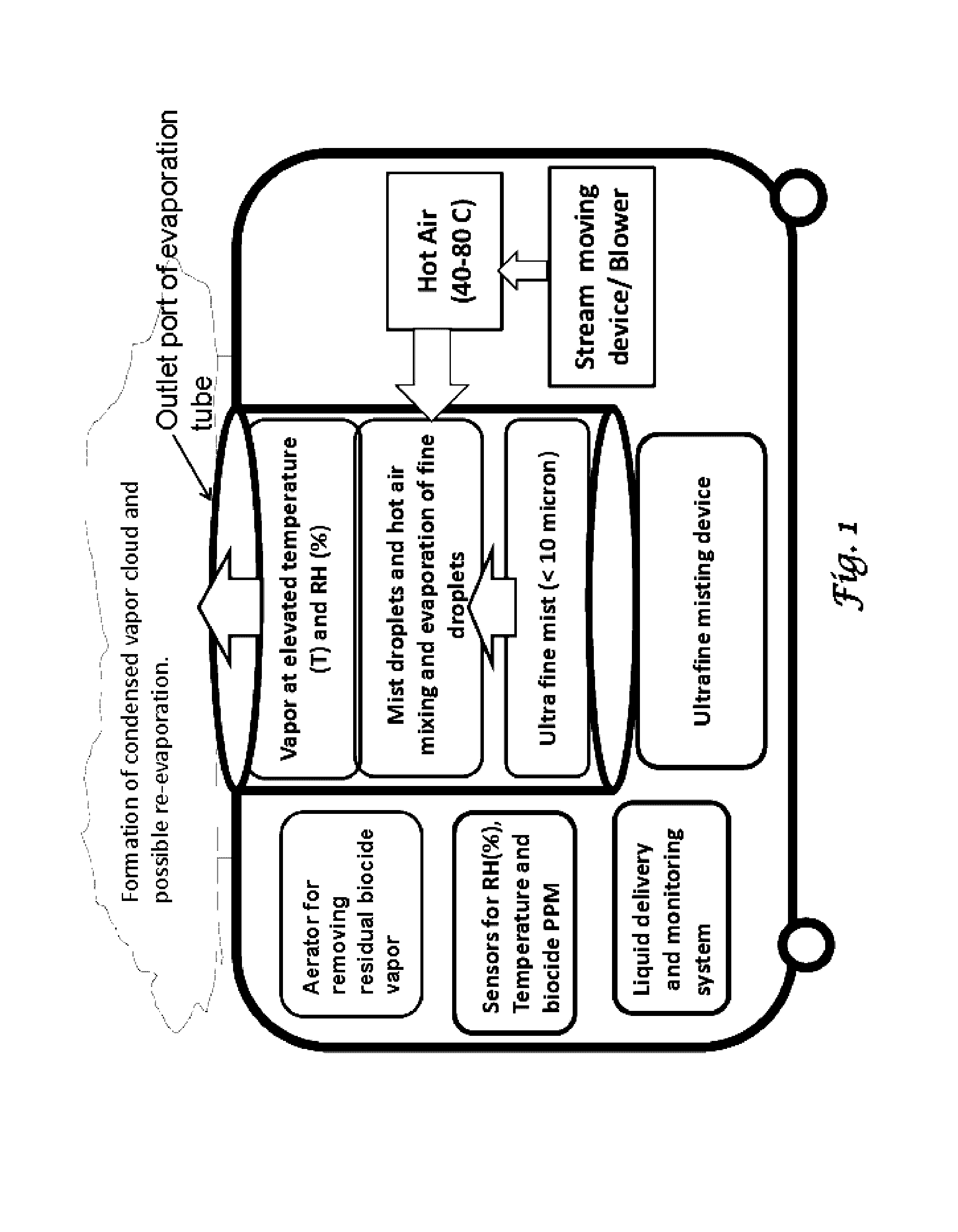
[0051]FIG. 1 shows a flow chart of the present inventive method for producing a condensed vapor cloud for decontamination of a volume and its contents. In a preferred embodiment, monodisperse ultrafine mist of a biocide or other solution is produced using an ultrasonic or suitable atomizer device and carried to the inlet of the evaporator enclosure. Separately, an air movement device is used to transport a gas through a he...


PUM

PropertyMeasurementUnit
mass concentrationaaaaaaaaaa
diametersaaaaaaaaaa
particle diametersaaaaaaaaaa

Abstract

A mist generator is used to deliver a high throughput extremely fine mist comprising a biocide. Flows of evaporating hot gas mix turbulently and enhance forced heat and mass transfer between the very fine droplets and the hot gas to form a well-mixed premixed evaporator, resulting in high humidity vapor formation well inside a tube. The high relative humidity vapor with elevated temperature is then condensed as it exits the tube and disperses into the volume to be decontaminated as a condensed vapor cloud, but neither as a mist nor as a pure vapor depending on temperature and humidity of room environment. The condensed vapor cloud may evaporate or settle on the volume surfaces and contents, whereby both dry vapor and condensed vapor are applied into the volume for the killing process.

Description

CROSS-REFERENCE TO PRIOR APPLICATIONS[0001]The present application claims priority to U.S. Patent Application 61 / 801,731 filed Mar. 15, 2013, which is incorporated by reference in its entirety.FIELD OF INVENTION[0002]This invention relates to a device and a method for decontaminating a volume, and more particularly, a method and device for producing low temperature, high throughput condensed vapor clouds of biocide liquids and air using an ultra-fine mist evaporator, and discharging the biocide—air mixture into the environment or volume to be decontaminated. The biocide is deployed as aggregates of a condensed vapor cloud mixture comprising a liquid biocide concentration or composition different from the starting liquid. The condensed vapor cloud, upon exposure to the environment and depending on the humidity and temperature of the environment, may evaporate into vapor or may remain as fine condensed vapor droplets, either of which or a combination of which, can be used for the deco...

Claims


Application Information

Patent Timeline
Patent Type & Authority Patents(United States)
IPC IPC(8): A61L9/00A62B7/08A61L2/22
CPCA61L2/22A61L2/186A61L9/14A61L2202/25A61L2209/16A61L2209/211
Inventor ADIGA, KAYYANI C.HATCHER, ROBERT F.ADIGA, RAJANI
Owner NANOMIST SYST
Why Eureka
Try Eureka