
Ceramic heater and method for producing the same

a ceramic heater and ceramic technology, applied in ceramic layered products, ohmic resistance heating, chemistry apparatus and processes, etc., can solve the problems of reducing the thermal uniformity of the wafer surface during plasma etching, the electric resistance occurred, and the temperature control of the ceramic heater is complicated, so as to achieve easy production, easy to produce, and easy to produce.

Active Publication Date: 2017-01-03
NGK INSULATORS LTD
View PDF5 Cites 0 Cited by
  • Summary
  • Abstract
  • Description
  • Claims
  • Application Information

AI Technical Summary

Benefits of technology

This patent aims to solve issues with ceramic heaters by improving the stability of resistance and reducing variations in resistivity. By using a heater electrode with a main component of TiSi2, the issue of reversal of temperature-dependent resistivity is improved. The use of a ceramic base composed of alumina with magnesium fluoride also helps to reduce the firing temperature. The invention also provides methods for easily producing the ceramic heater and ensures uniform density and without warping. The ceramic molded bodies are prepared using a gel-casting method. Overall, the present invention enhances the performance and reliability of ceramic heaters.

Problems solved by technology

However, in the case where a molybdenum paste was used, an undesirable problem in terms of the relationship among a preset temperature, a distance from the center of a ceramic heater, and electrical resistivity occurred.
The occurrence of this reversal phenomenon is not preferable because it becomes very complicated to control the temperature of the ceramic heater.
In the case where molybdenum containing a titanium component is used as a material of a heater electrode, although the phenomenon of reversal of temperature-dependence of resistivity is improved, the in-plane variation of the electrical resistivity cannot be sufficiently suppressed, resulting in a problem of a decrease in thermal uniformity of a wafer surface during plasma etching.

Method used


Image

  • Ceramic heater and method for producing the same
  • Ceramic heater and method for producing the same
  • Ceramic heater and method for producing the same

Examples


example 1

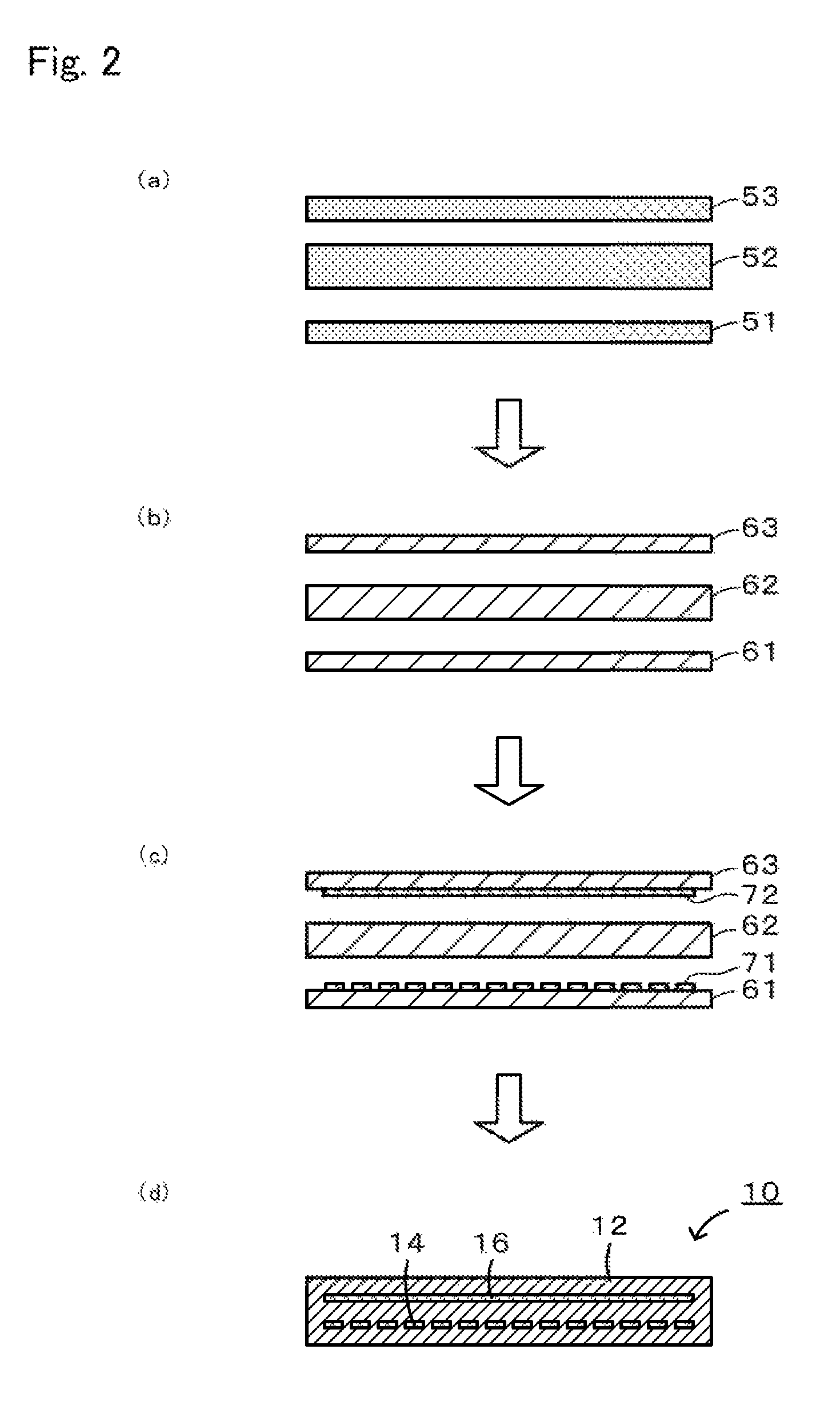
[0061]An electrostatic chuck 10 was produced by the first production procedure described above (refer to FIG. 2).

(a) Preparation of Molded Bodies

[0062]One hundred parts by weight of an alumina powder (average particle diameter: 0.5 μm, purity: 99.99%), 0.2 parts by weight of magnesia, 0.3 parts by weight of magnesium fluoride, 3 parts by weight of a polycarboxylic acid copolymer serving as a dispersant, and 20 parts by weight of a polybasic acid ester serving as a solvent were weighed. These components were mixed using a ball mill (trommel) for 14 hours to prepare a slurry precursor. A gelling agent containing, namely, 3.3 parts by weight of 4,4′-diphenylmethane diisocyanate serving as an isocyanate, 0.3 parts by weight of ethylene glycol serving as a polyol, and 0.1 parts by weight of 6-dimethylamino-1-hexanol serving as a catalyst was added to the slurry precursor, and the resulting mixture was mixed using a rotary and revolutionary stirrer for 12 minutes to prepare a slurry. The ...


PUM

PropertyMeasurementUnit
temperatureaaaaaaaaaa
degreasing temperatureaaaaaaaaaa

Abstract

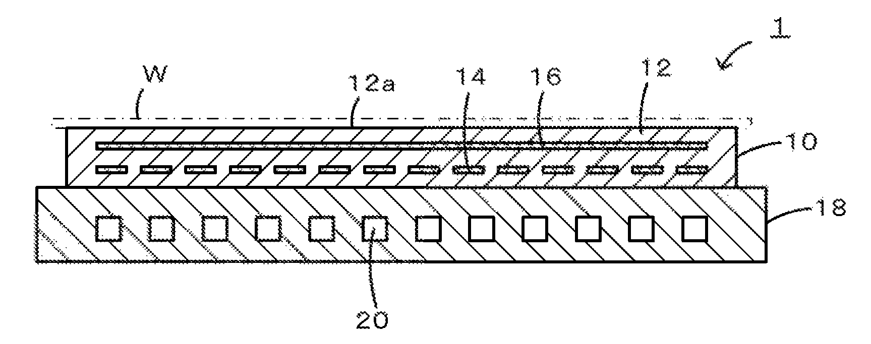
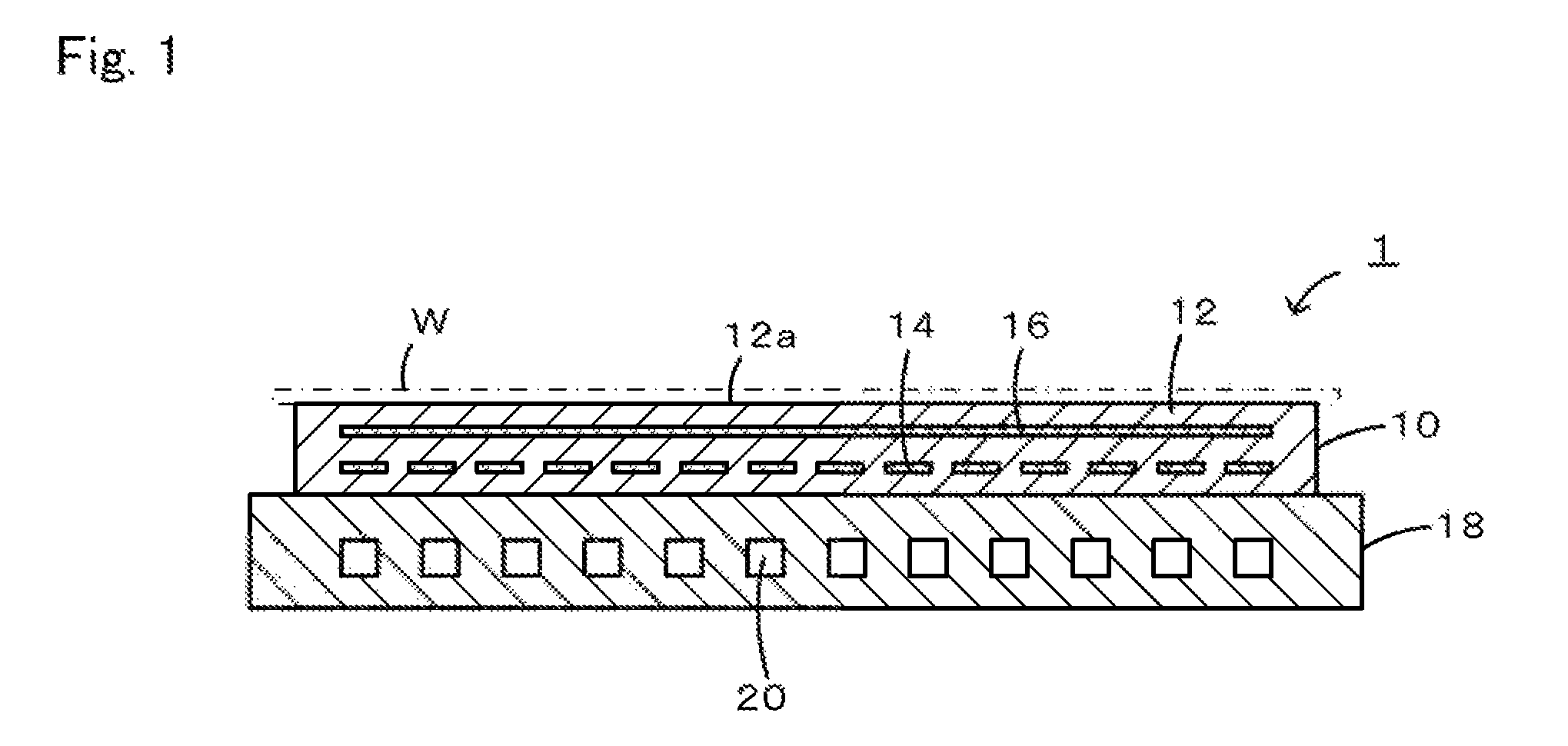
An electrostatic chuck 10 includes a disc-shaped alumina ceramic base 12, and a heater electrode 14 and an electrostatic electrode 16 that are embedded in the alumina ceramic base 12. An upper surface of the alumina ceramic base 12 functions as a wafer-receiving surface 12a. The heater electrode 14 is formed in a pattern shape, for example, in the manner of a single brush stroke so as to be arranged over the entire surface of the alumina ceramic base 12. When a voltage is applied to the heater electrode 14, the heater electrode 14 generates heat, and heats a wafer W. This heater electrode 14 contains TiSi2 as a main component.

Description

BACKGROUND OF THE INVENTION[0001]1. Field of the Invention[0002]The present invention relates to a ceramic heater and a method for producing the same.[0003]2. Description of the Related Art[0004]A known ceramic heater used for heating a semiconductor wafer is a disc-shaped alumina sintered body in which a heater electrode is embedded. For example, PTL 1 discloses a method for obtaining a ceramic heater, the method including preparing two molded bodies obtained by molding a mixed powder of alumina and magnesium fluoride so as to have a predetermined shape, arranging, on one of the molded bodies, a paste which is to become a heater electrode, then stacking the other molded body, and conducting firing at a low firing temperature of 1,120° C. to 1,300° C. In the production process of a ceramic heater, in the case where high-temperature firing at 1,700° C. is conducted, when tungsten carbide (WC) is used as a paste, WC is sufficiently sintered and appropriate electrical properties of a h...

Claims


Application Information

Patent Timeline
Patent Type & Authority Patents(United States)
IPC IPC(8): H05B3/10C04B35/111B32B18/00H01L21/683H05B3/14H01L21/67C04B35/645
CPCC04B35/645B32B18/00C04B35/111H01L21/67103H01L21/6831H05B3/143C04B2235/3206C04B2235/3217C04B2235/445C04B2235/5445C04B2235/606C04B2235/6023C04B2235/6567C04B2235/6581C04B2235/72C04B2237/08C04B2237/343C04B2237/36C04B2237/595C04B2237/68H05B2203/017
Inventor NOBORI, KAZUHIROKIMURA, TAKUJINAKAGAWA, HIDEMI
Owner NGK INSULATORS LTD
Learn More