Stirling cycle machine with airlock pressure regulator and burner controls

a technology of airlock and burner control, which is applied in the field of machines, can solve the problems of increasing engine noise, increasing piston wear, and reducing engine efficiency and li

Active Publication Date: 2017-01-03
DEKA PROD LLP
View PDF16 Cites 2 Cited by
  • Summary
  • Abstract
  • Description
  • Claims
  • Application Information

AI Technical Summary

Problems solved by technology

A common problem encountered with such machines is that of friction generated by a sliding piston resulting from misalignment of the piston in the cylinder and lateral forces exerted on the piston by linkage of the piston to a rotating crankshaft.
These increased side loads increase engine noise, increase piston wear, and decrease the efficiency and life of the engine.
Additionally, because of the side loads, the drive requires more power to overcome these frictional forces, thus reducing the efficiency of the machine.
Improvements have been made on drive mechanisms in an attempt to reduce these side loads, however, many of the improvements have resulted in heavier and bulkier machines.

Method used


Image

  • Stirling cycle machine with airlock pressure regulator and burner controls
  • Stirling cycle machine with airlock pressure regulator and burner controls
  • Stirling cycle machine with airlock pressure regulator and burner controls

Examples


Embodiment Construction

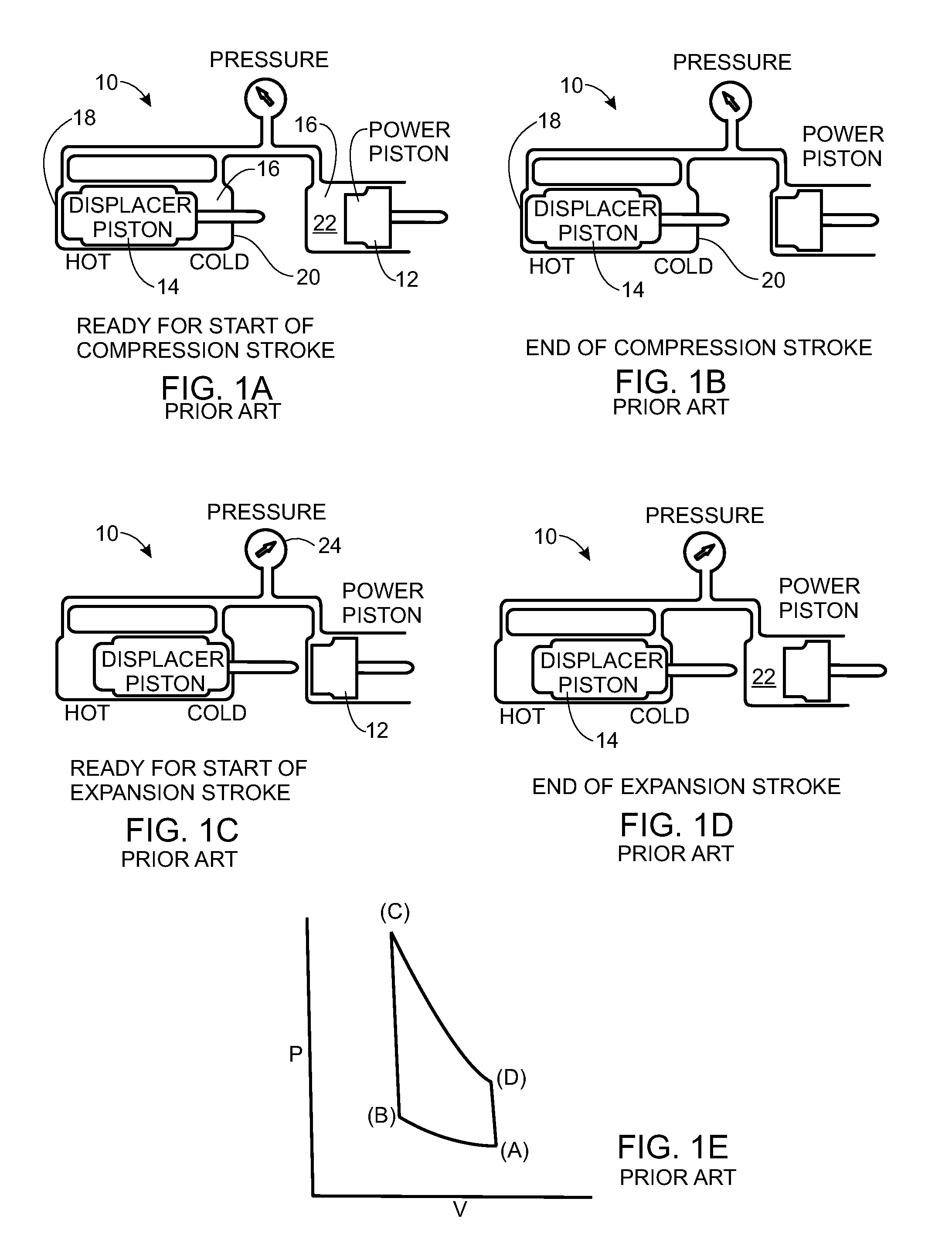
[0204]Stirling cycle machines, including engines and refrigerators, have a long technological heritage, described in detail in Walker, Stirling Engines, Oxford University Press (1980), incorporated herein by reference. The principle underlying the Stirling cycle engine is the mechanical realization of the Stirling thermodynamic cycle: isovolumetric heating of a gas within a cylinder, isothermal expansion of the gas (during which work is performed by driving a piston), isovolumetric cooling, and isothermal compression. Additional background regarding aspects of Stirling cycle machines and improvements thereto is discussed in Hargreaves, The Phillips Stirling Engine (Elsevier, Amsterdam, 1991), which is herein incorporated by reference.

[0205]The principle of operation of a Stirling cycle machine is readily described with reference to FIGS. 1A-1E, wherein identical numerals are used to identify the same or similar parts. Many mechanical layouts of Stirling cycle machines are known in t...


PUM


Abstract

An external combustion engine is disclosed. The external combustion engine includes a working fluid and a burner element, at least one heater head defining a working space, at least one piston cylinder containing a piston, a cooler, a crankcase including a crankshaft for producing an engine output, a rocking beam, a piston rod connected to the piston, a rocking beam driven by the piston rod, and a connecting rod connected at a first end to the rocking beam and at a second end to a crankshaft to convert rotary motion of the rocking beam to rotary motion of the crankshaft. The external combustion engine also includes an airlock space separating the crankcase and the working space for maintaining a pressure differential between the crankcase housing and the working space housing and an airlock pressure regulator connected between the crankcase and one of the airlock space and working space.

Description

CROSS REFERENCE TO RELATED APPLICATIONS[0001]The present application is a Non-Provisional Application which claims the benefits of U.S. Provisional Patent Application Ser. No. 61 / 476,180, filed Apr. 15, 2011 and entitled Stirling Cycle Machine, and U.S. Provisional Patent Application Ser. No. 61 / 482,897, filed May 5, 2011 and entitled Stirling Cycle Machine, both of which are hereby incorporated herein by reference in their entireties.[0002]This application is also a Continuation In Part application of U.S. patent application Ser. No. 12 / 829,320, filed Jul. 1, 2010 and entitled Stirling Cycle Machine, now U.S. Publication No. US-2011-0011078-A1, published Jan. 20, 2011, which claims the benefit of U.S. Provisional Patent Application Ser. No. 61 / 222,361, filed Jul. 1, 2009 and entitled Stirling Cycle Machine, both of which are hereby incorporated herein by reference in their entireties.TECHNICAL FIELD[0003]The present invention relates to machines and more particularly, to a Stirling...

Claims


Application Information

Patent Timeline
Patent Type & Authority Patents(United States)
IPC IPC(8): F02G1/044F28F1/14F28F1/12F28D7/06F28D7/02F28F27/00F28F13/06F28F9/02F28F1/42F28F1/40F02G1/053F01K25/00F02C3/00F16J15/52F28D17/02
CPCF02G1/044F01K25/00F28F9/026F28F13/06F28F27/00F02G1/0535F28D7/024F28D7/06F28F1/124F28F1/126F28F1/14F28F1/40F28F1/42F02C3/00F02G2244/52F02G2244/54F02G2253/06F02G2253/08F02G2253/10F02G2254/10F02G2254/50F02G2254/60F02G2256/04F02G2257/00F02G2270/40F02G2270/50F02G2270/85F16J15/52F28D17/02F28F2255/14
Inventor KAMEN, DEANLANGENFELD, CHRISTOPHER C.BHAT, PRASHANTNORRIS, MICHAEL G.
Owner DEKA PROD LLP
Why Eureka
Try Eureka