Structured illuminating microscopy and structured illuminating observation method

a structure illuminating and microscopy technology, applied in the direction of instruments, optical elements, fluorescence/phosphorescence, etc., can solve the problem of reducing the time taken to obtain all the required images, and achieve the effect of expanding the structure direction

Active Publication Date: 2017-01-03
NIKON CORP
View PDF11 Cites 4 Cited by
  • Summary
  • Abstract
  • Description
  • Claims
  • Application Information

AI Technical Summary

Problems solved by technology

However, when an optical element is moved in steps, a certain period of time is required for stopping the moving optical element at an appropriate position, so that it is difficult, in the method of Patent Document 2, to reduce a period of time taken for obtaining all of the required images.

Method used


Image

  • Structured illuminating microscopy and structured illuminating observation method
  • Structured illuminating microscopy and structured illuminating observation method
  • Structured illuminating microscopy and structured illuminating observation method

Examples


Embodiment Construction

[0029]Hereinafter, a structured illuminating microscopy system will be described as an embodiment of the present invention.

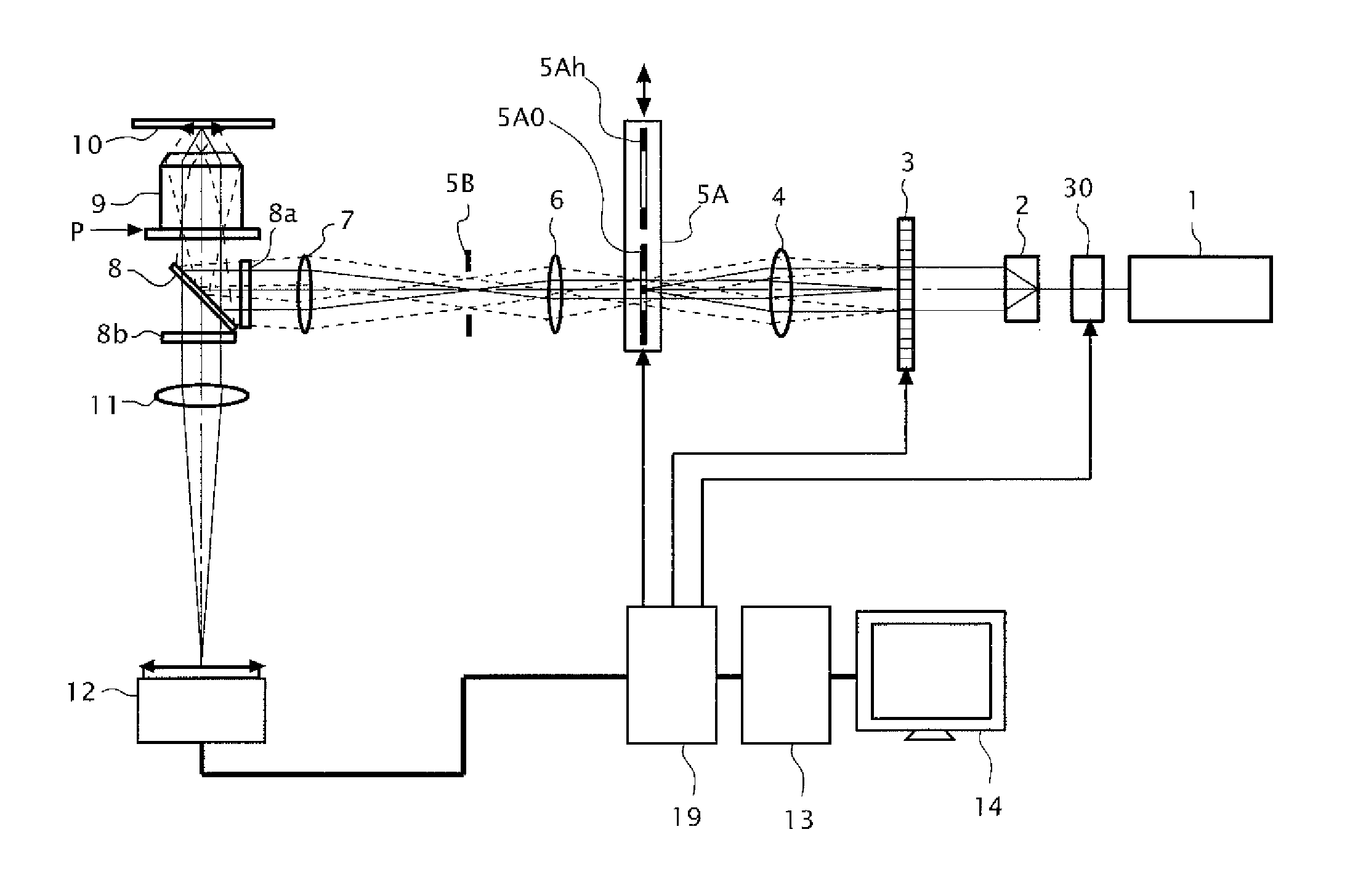
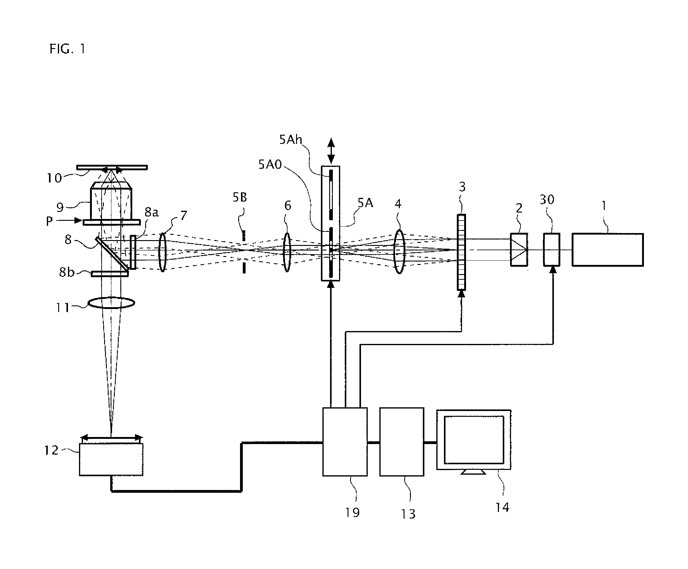
[0030]FIG. 1 is a configuration diagram of a structured illuminating microscopy system of the present embodiment. As illustrated in FIG. 1, in the present system, there are disposed a coherent light source 1, a light intensity modulator 30, a collector lens 2, an ultrasonic wave spatial light modulator 3, a lens 4, a mask switching mechanism 5A, a lens 6, a field stop 5B, a lens 7, an excitation filter 8a, a dichroic mirror 8, a fluorescence filter 8b, a second objective lens 11, an imaging device (CCD camera or the like) 12, a controlling device 19, an image storing-calculating device (computer or the like) 13, an image displaying device 14, and an objective lens 9. Note that a reference numeral 10 in FIG. 1 denotes a specimen placed on a not-illustrated stage, and in this case, it is assumed that the specimen is previously fluorescent-stained.

[0031]The coheren...


PUM

PropertyMeasurementUnit
resolving powersaaaaaaaaaa
lengthaaaaaaaaaa
diameteraaaaaaaaaa

Abstract

In order to realize a high-speed switching of structured pattern, a structured illuminating microscopy includes a driving unit generating a sonic standing wave in a sonic wave propagation path by giving a driving signal for vibrating a medium of the sonic wave propagation path to a light modulator, an illuminating optical system making at least three diffracted components of the exit light flux passed through the sonic wave propagation path to be interfered with one another, and forming interference fringes on an observational object, an image-forming optical system forming an image by an observational light flux from the observational object on a detector, and a controlling unit controlling a contrast of an image by modulating at least one of an intensity of the exit light flux, an intensity of the observational light flux, and the detector with a modulating signal of 1 / N frequency of the driving signal.

Description

CROSS REFERENCE TO RELATED APPLICATION[0001]This application is a continuation application of International Application No. PCT / JP2012 / 002946, filed on May 1, 2012, designating the U.S., and claims the benefit of priority from Japanese Patent Application No. 2011-103652, filed on May 6, 2011, the entire contents of which are incorporated herein by reference.BACKGROUND[0002]1. Field[0003]The present application relates to a structured illuminating microscopy and a structured illuminating observation method.[0004]2. Description of the Related Art[0005]A super-resolution microscopy is one that modulates an illumination light flux that illuminates a sample plane and demodulates an image-forming light flux which is incident on a position that is substantially conjugated with the sample plane of an image-forming optical system, in order to make information regarding a high spatial frequency that exceeds a resolution limit (diffracted light at a large angle) out of diffracted light that ex...

Claims


Application Information

Patent Timeline
Patent Type & Authority Patents(United States)
IPC IPC(8): G02B21/06G02B21/14G01N21/64
CPCG02B21/06G02B21/14G01N21/6456
Inventor NOMURA, TATSUSHIOSAWA, HISAOFUKUTAKE, NAOKI
Owner NIKON CORP
Why Eureka
Try Eureka