Air conditioner for vehicle
a technology for air conditioners and vehicles, applied in vehicle components, vehicle heating/cooling devices, air-treatment apparatus arrangements, etc., can solve the problems of low efficiency, difficult to arrange the two indoor units in the air-conditioning case, and the temperature of the cooling water cannot be kept constan
- Summary
- Abstract
- Description
- Claims
- Application Information
AI Technical Summary
Benefits of technology
Problems solved by technology
Method used
Image
Examples
first embodiment
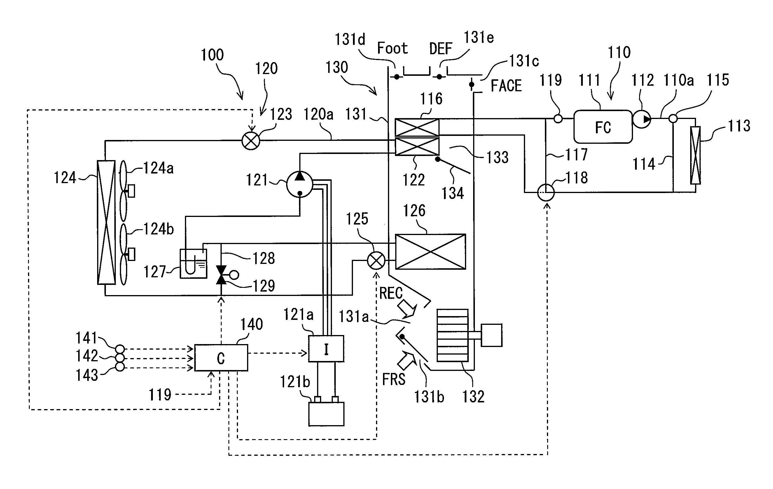
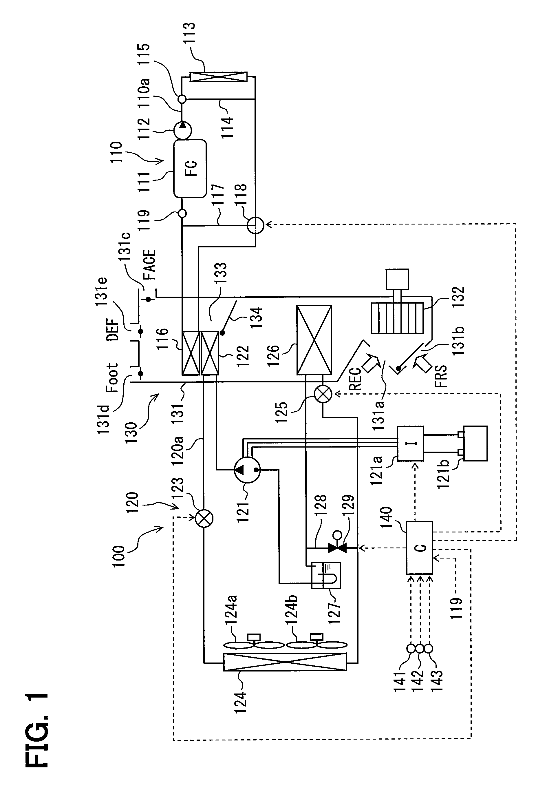
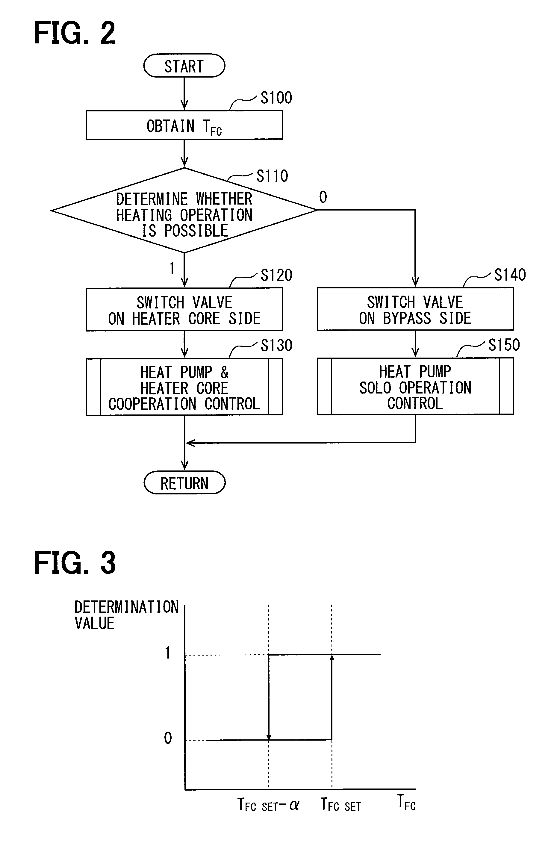
[0040]Hereafter, an air-conditioner 100 for a vehicle according to a first embodiment is explained with reference to FIGS. 1-4.
[0041]As shown in FIG. 1, the air-conditioner 100 is mounted to a fuel-cell vehicle (electric car EV) driven by, for example, a motor as a drive source. The vehicle includes a fuel cell 111 which supplies electric power to the motor. The air-conditioner 100 is equipped with a heater core 116 placed in a cooling circuit 110 which cools the fuel cell 111, a heat pump cycle 120, an indoor unit 130, and a control device 140.
[0042]The cooling circuit 110 is a circuit for cooling the fuel cell 111, and has a circulation passage 110a through which the cooling water circulates. The fuel cell 111, a pump 112, a radiator 113, a bypass channel 114, a switch valve 115, the heater core 116, a bypass channel 117, a switch valve 118, and a water temperature sensor 119 are arranged in the circulation passage 110a.
[0043]The fuel cell 111 is a battery which generates electri...
second embodiment
[0110]A determination map of a second embodiment is shown in FIG. 6. The determination map is modified in the second embodiment, compared with the first embodiment.
[0111]As shown in FIG. 6, in the determination map, when the cooling water temperature TFC becomes lower than the heating possible temperature TFC SET, the target value TAVO of the blow-off temperature is set as the same value as the cooling water temperature TFC by the control device 140.
[0112]Thereby, when the cooling water temperature TFC is lower than the heating possible temperature TFC SET, there is no difference between the temperature of the air for air-conditioning heated by the indoor heat exchanger 122 and the cooling water temperature TFC in the heater core 116. Therefore, the heat of the cooling water in the heater core 116 is not emitted to the air for air-conditioning, and the heat of cooling water can be maintained in the cooling circuit 110. That is, the temperature of the fuel cell 111 can be kept consta...
third embodiment
[0113]A determination map of a third embodiment is shown in FIG. 7. The determination map is modified in the third embodiment, compared with the first embodiment.
[0114]As shown in FIG. 7, in the determination map, when the cooling water temperature TFC becomes lower than the heating possible temperature TFC SET, the target value TAVO of the blow-off temperature is set as a value higher than the cooling water temperature TFC by the control device 140. Specifically, the target value TAVO of the blow-off temperature is set as a value in the hatched area shown in FIG. 7.
[0115]Thereby, similar to the double line part explained with reference to FIG. 5 in the first embodiment, when the cooling water temperature TFC is lower than the heating possible temperature TFC SET, the temperature of the air for air-conditioning heated by the indoor heat exchanger 122 always becomes higher than the cooling water temperature TFC. Therefore, the cooling water in the heater core 116 which is located dow...
PUM
 Abstract
Description
Claims
Application Information
 - R&D
- Intellectual Property
- Life Sciences
- Materials
- Tech Scout
- Unparalleled Data Quality
- Higher Quality Content
- 60% Fewer Hallucinations
Browse by: Latest US Patents, China's latest patents, Technical Efficacy Thesaurus, Application Domain, Technology Topic, Popular Technical Reports.
© 2025 PatSnap. All rights reserved.Legal|Privacy policy|Modern Slavery Act Transparency Statement|Sitemap|About US| Contact US: help@patsnap.com


