
Subframe for a motor vehicle

a technology for subframes and motor vehicles, applied in the direction of vehicle components, interconnection systems, resilient suspensions, etc., can solve the problems of affecting the the additional installation space of the rotary actuator in the vehicle front, and the limited space of the vehicle front, so as to achieve the effect of simple and lightweight construction, high bending stiffness of the subframe cross member

Active Publication Date: 2017-01-10
AUDI AG
View PDF25 Cites 2 Cited by
  • Summary
  • Abstract
  • Description
  • Claims
  • Application Information

AI Technical Summary

Benefits of technology

The invention is a subframe for a motor vehicle that allows for better arrangement of adjacent functional parts without compromising its strength. The subframe includes two front node elements connected by a front subframe cross member, and at least one functional part, such as a rotary actuator, that extends close to the cross member for better spatial utilization. The cross member has an opening to provide additional installation space for the functional part without reducing its bending stiffness. The subframe is designed to be lightweight and simple in construction. Overall, the invention provides a compact and stiff subframe design for motor vehicles that allows for optimal arrangement of functional parts.

Problems solved by technology

The rotary actuator requires additional installation space in the vehicle front which, however, is very limited due to the high space requirements for the drive units.
However, such a flat profile arrangement adversely affects the stiffness of the subframe.

Method used


Image

  • Subframe for a motor vehicle
  • Subframe for a motor vehicle
  • Subframe for a motor vehicle

Examples


Embodiment Construction

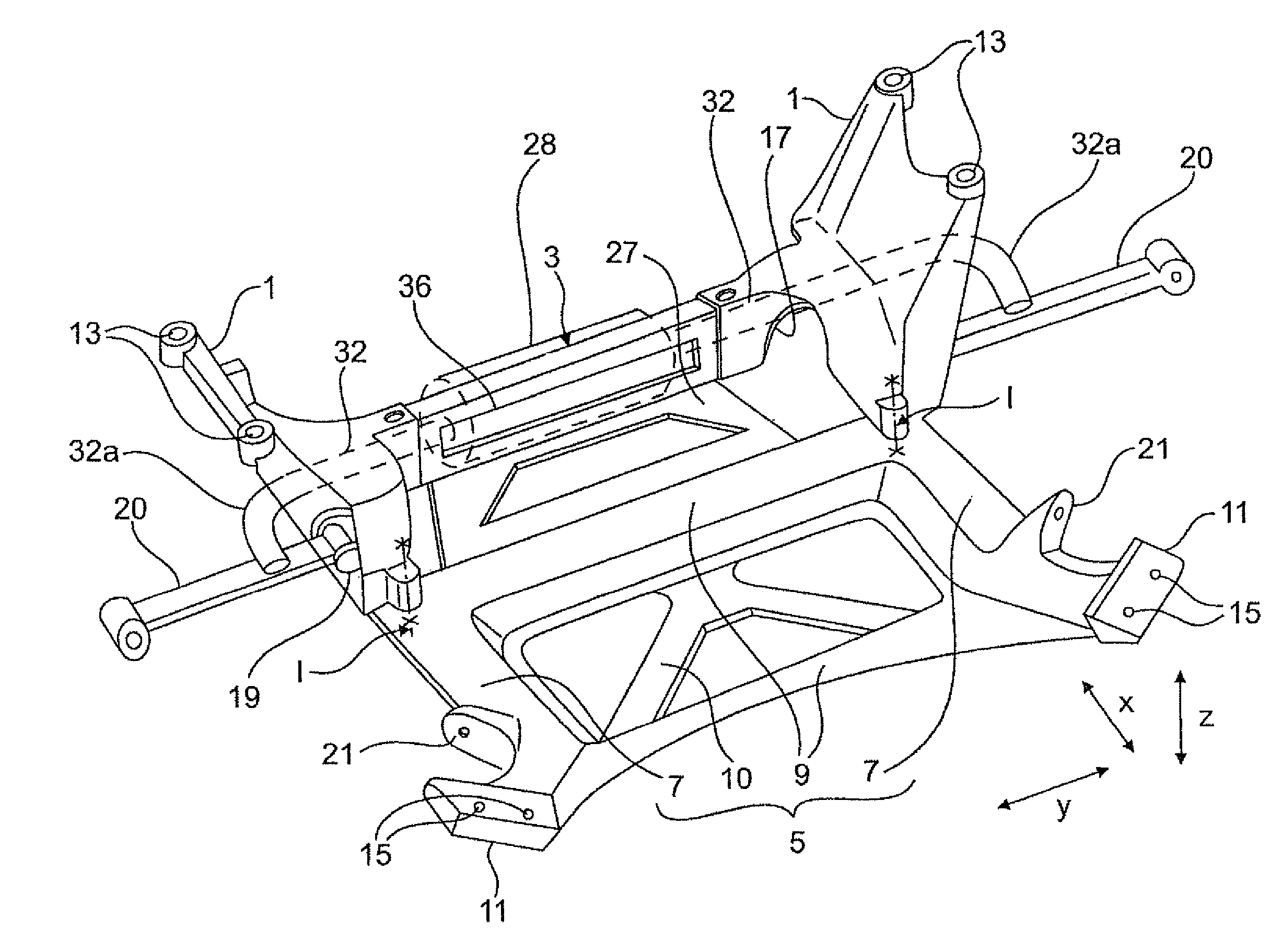
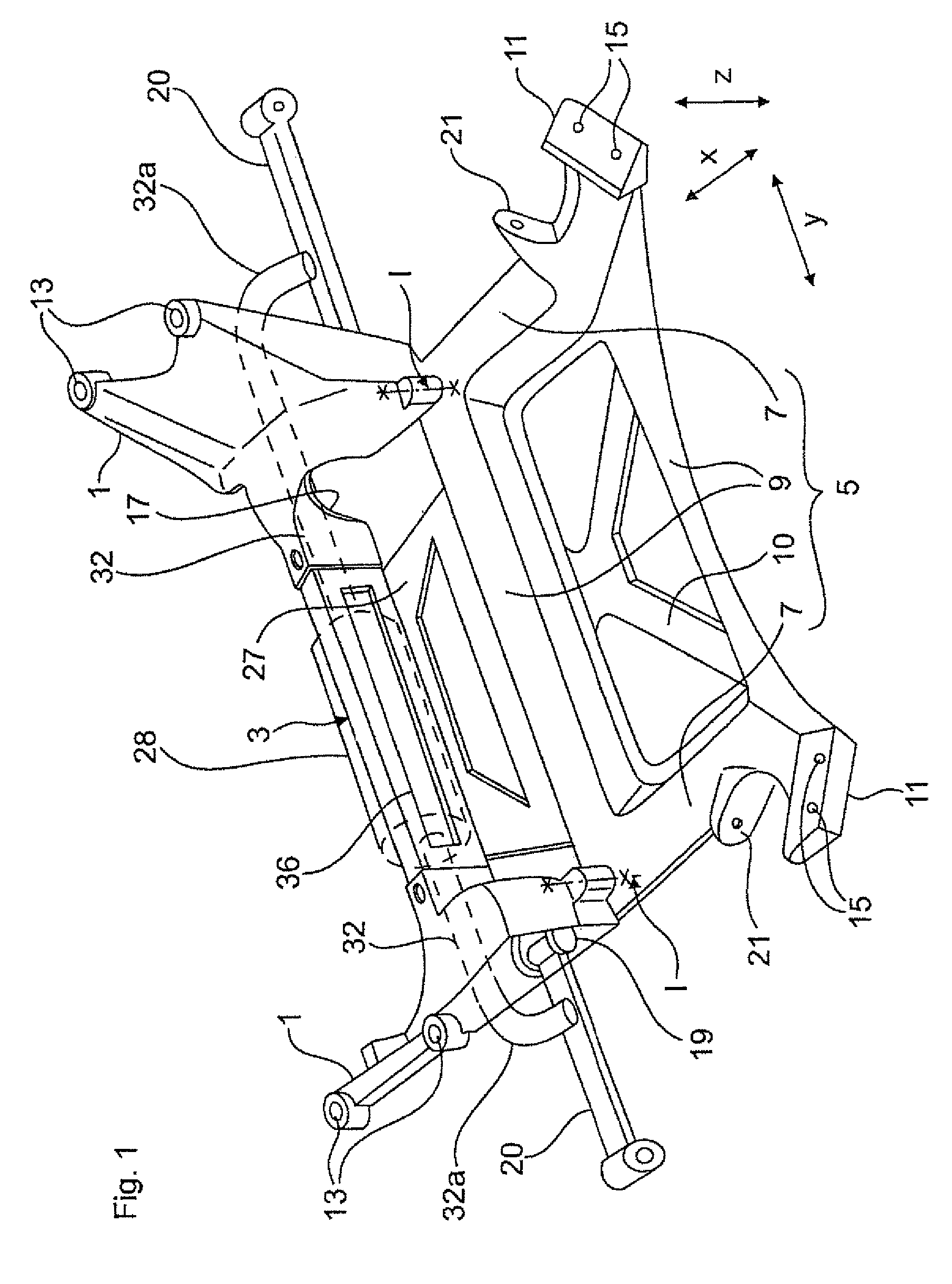
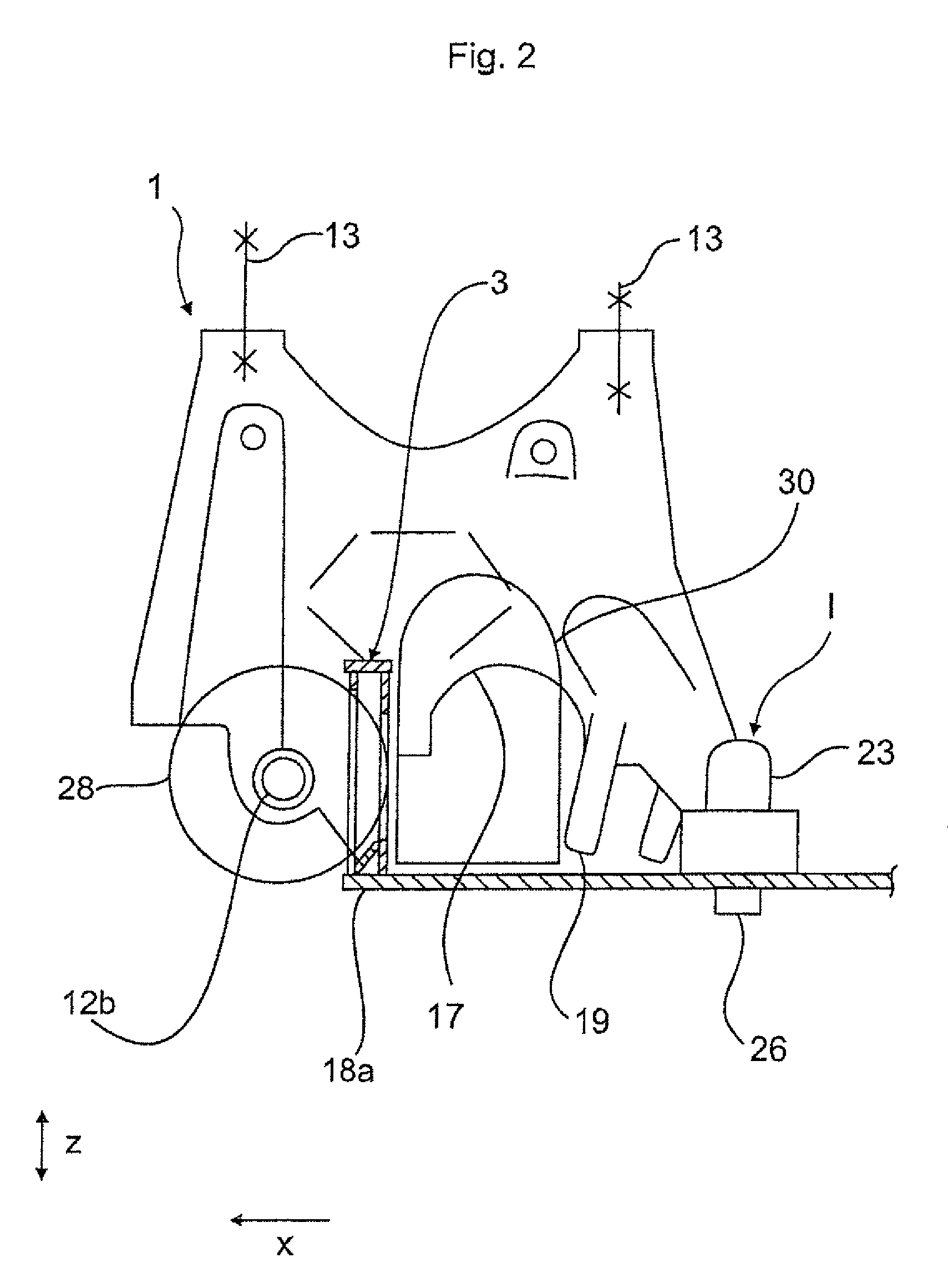
[0031]FIG. 1 shows a subframe in isolation. The subframe has in the vehicle longitudinal direction x on either side front node elements 1, which are formed here by way of example as box-shaped aluminum cast nodes. The two node elements 1 are connected in the vehicle transverse direction y with a subframe cross member 3. Adjoining the two front cast nodes 1 in the vehicle longitudinal direction x to the rear is a flat, plate-shaped reinforcement element 5 which is configured substantially like a framework with longitudinal struts 7, transverse struts 9, and diagonal struts 10. Rear node elements 11 are formed integrally on the reinforcement element 5 of same material and in one piece at the rear end of the reinforcement element 5.

[0032]The two front node elements 1 have each on the upper side screw holes 13 for connection to a not shown body longitudinal member. Conversely, the two rear node elements 11 have each screw holes 15 for connection to the longitudinal member at the base of...


PUM


Abstract

The invention relates to a subframe for a motor vehicle, comprising two front node elements (1) for connecting to a vehicle body, which node elements are spaced from each other in a vehicle transverse direction (y) and are connected to each other by means of a front subframe cross member (3), and comprising at least one functional part (28), in particular a rotary actuator, which extends adjacently to the subframe cross member (3) in a vehicle transverse direction (y), by means of which functional part a torsion can be applied to torsion springs that act on the vehicle wheel suspension. According to the invention, the subframe cross member (3) has an opening, which provides an additional installation space, in which the functional part (28) at least partially protrudes.

Description

CROSS-REFERENCES TO RELATED APPLICATIONS[0001]This application is the U.S. National Stage of International Application No. PCT / EP2014 / 002039, filed Jul. 25, 2014, which designated the United States and has been published as International Publication No. WO 2015 / 018501 and which claims priority of German Patent Application, Serial No. 10 2013 013 325.4, filed Aug. 9, 2013, pursuant to 35 U.S.C. 119(a)-(d).BACKGROUND OF THE INVENTION[0002]The present invention relates to a subframe for a motor vehicle.[0003]DE 102 29 161 B4 discloses such a subframe for a motor vehicle. Bolted to the front subframe cross member of the subframe is the housing of a rack-and-pinion steering. For this purpose, bearing mounts in the form of half-shells are provided on the subframe cross member, configured as upright profile, for securement of the steering housing which is approximately circular-symmetrical in cross section. The subframe cross member is rigid as a result of the rectangular cross sectional s...

Claims


Application Information

Patent Timeline
IPC IPC(8): B62D21/11B60G11/18B60G21/055
CPCB62D21/11B60G11/181B60G21/0555B60G2204/122B60G2204/1222B60G2204/15
Inventor KRAMER, TOBIASBOSCH, JAKOB
Owner AUDI AG
Learn More