Method for liquefying natural gas with a triple closed circuit of coolant gas

a technology of closed circuit and natural gas, applied in the field of process for liquefying natural gas, can solve the problems of large equipment, large footprint, and large amount of gas, and achieve the effects of reducing the total energy consumed by the process, and increasing the heat transfer

Active Publication Date: 2017-01-31
SAIPEM SA
View PDF6 Cites 2 Cited by
  • Summary
  • Abstract
  • Description
  • Claims
  • Application Information

AI Technical Summary

Benefits of technology

[0048]An object of the present invention is to provide a natural gas liquefaction process of the type with no phase change in the refrigerant gas that is suitable for being installed on board a ship or a floating support and that presents improved energy efficiency, i.e. that mini

Problems solved by technology

Said first cycle type with a change of phase is generally used in installations on land and it requires a large amount of equipment and occupies a large footprint.
In addition, the refrigerant fluids, generally in the form of mixtures, are constituted by butane, propane, ethane, and methane, which gases are dangerous since in the event of a leak they run the risk of leading to substantial fires or explosions.
The complexity of those installations comes from the fact that in those stages where the refrigerant fluid is in the liquid state, and more particularly in separators and in connection pipes, it is appropriate to install gravity collectors in order to bring the liquid phase together and direct it to the cores of heat exchangers where it vaporizes on coming into contact with the methane for cooling and liquefying in order to obtain LNG.
Managing a process with a phase change invol

Method used


Image

  • Method for liquefying natural gas with a triple closed circuit of coolant gas
  • Method for liquefying natural gas with a triple closed circuit of coolant gas
  • Method for liquefying natural gas with a triple closed circuit of coolant gas

Examples


Embodiment Construction

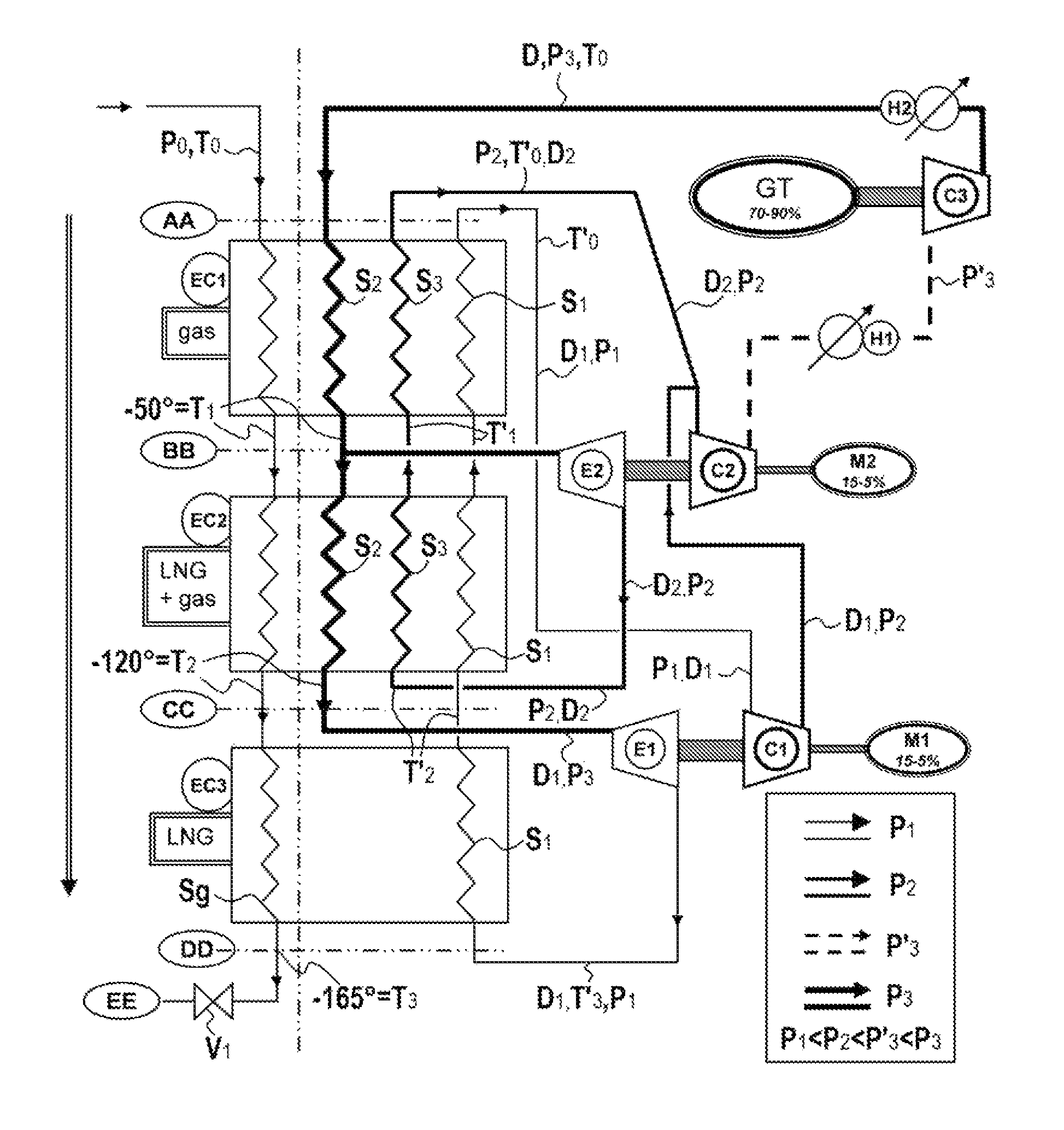
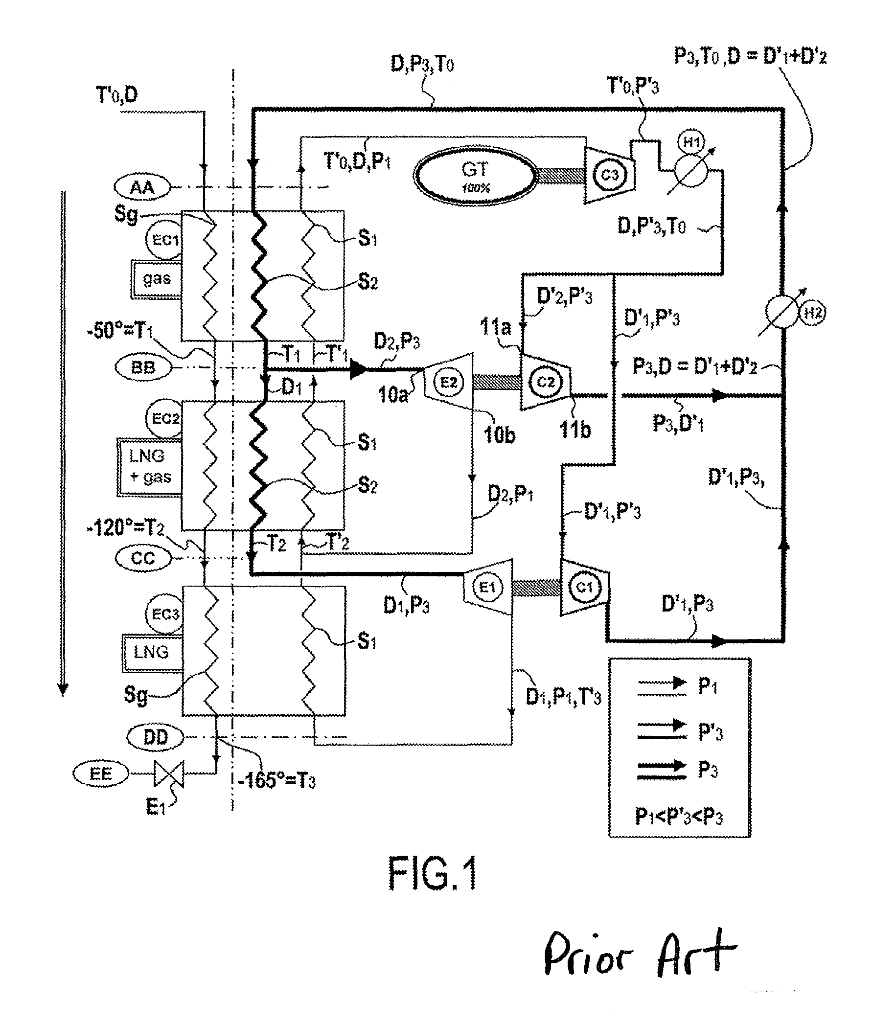
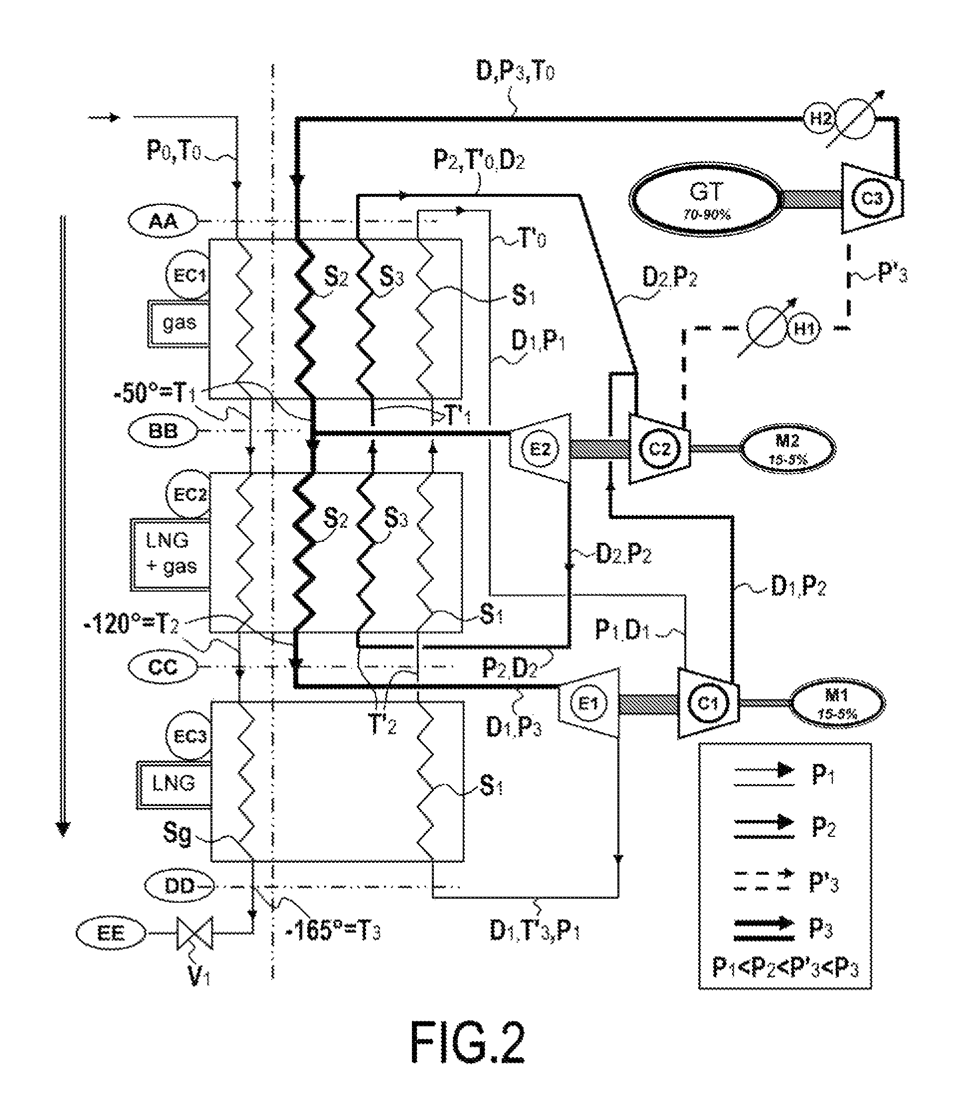
[0156]FIG. 1 is a process flow diagram (PFD) for the standard double loop process without phase change using nitrogen as the refrigerant gas. The process uses compressors C1, C2, and C3, expanders E1 and E2, intermediate coolers H1 and H2, and cryogenic heat exchangers EC1, EC2, and EC3. In known manner, the heat exchangers are constituted by at least two circuits that are juxtaposed but that do not communicate with each other in terms of said fluids, the fluids flowing in said circuits exchanging heat all along their paths within such a heat exchanger. Numerous types of heat exchanger have been developed in various industries and in the context of cryogenic heat exchangers, two main types predominate: firstly coiled heat exchangers; and secondly brazed aluminum plate heat exchangers, known as “cold box” heat exchangers.

[0157]Heat exchangers of this type are known to the person skilled in the art and they are sold by the suppliers Linde (France) or Five Cyrogénie (France). Thus, all...


PUM


Abstract

A process for liquefying natural gas by; a) causing it to flow through three series connected heat exchangers, where gas is cooled to T3; T3 is less/equal to the liquefaction temperature of natural gas at atmospheric pressure; and b) causing the closed circuit circulation of a first stream of refrigerant gas at a pressure P1 lower than P3 entering the third exchanger and leaving the first exchanger, the first stream obtained using a first expander to expand a first portion of a second stream at P3 higher than P2, the second stream flowing relative to the natural gas stream entering the first exchanger and leaving the second exchanger; and a third stream at a pressure P2 higher than P1 and lower than P3 flowing relative to the first stream, entering the second exchanger and leaving the first exchanger; c) the second stream at the pressure P3 obtained by compression.

Description

CROSS REFERENCE TO RELATED APPLICATIONS[0001]This is a U.S. national stage of application No. PCT / FR2012 / 051428, filed on Jun. 22, 2012. Priority is claimed on France Application No. FR1155595, filed Jun. 24, 2011, the content of which is incorporated herein by reference.FIELD OF THE INVENTION[0002]The present invention relates to a process for liquefying natural gas in order to produce liquefied natural gas (LNG). Still more particularly, the present invention relates to liquefying natural gas comprising a majority of methane, preferably at least 85% methane, with the other main constituents being selected from nitrogen and C-2 to C-4 alkanes, i.e. ethane, propane, and butane.[0003]The present invention also relates to a liquefaction installation on board a ship or a floating support at sea, either on the open sea or in a protected zone such as a port, or indeed an installation on land for small or medium natural gas liquefaction units.[0004]With an installation on board a ship, th...

Claims


Application Information

Patent Timeline
IPC IPC(8): F25J1/00F25J1/02
CPCF25J1/0022F25J1/005F25J1/0072F25J1/0097F25J1/0204F25J1/0212F25J1/0254F25J1/0283F25J1/0284F25J1/0285F25J1/0287F25J1/0288F25J1/0289F25J2230/22F25J2270/14F25J2270/16F25J1/0025F25J2230/20
Inventor BONNISSEL, MARCDU PARC, BERTRANDZIELINSKI, ERIC
Owner SAIPEM SA
Why Eureka
Try Eureka