Burner assembly and method of combustion

a technology of combustion and combustion chamber, which is applied in the direction of combustion process, gaseous fuel burner, liquid fuel burner, etc., can solve the problems of increasing the risk of hot spot formation in the furnace crown, the inability to eliminate all nitrogen from the furnace, so as to increase the flame stability, and enhance the effect of flame stability

Active Publication Date: 2017-02-14
LAIR LIQUIDE SA POUR LETUDE & LEXPLOITATION DES PROCEDES GEORGES CLAUDE
View PDF10 Cites 3 Cited by
  • Summary
  • Abstract
  • Description
  • Claims
  • Application Information

AI Technical Summary

Benefits of technology

[0130]Flame stability can also be increased by injection of one or more auxiliary oxidant jets through or in the vicinity of the outlets of the at least two fuel injection canals. According to a preferred embodiment, auxiliary oxidant jets are injected into the combustion zone through or in the vicinity of the outlets of the at least two fuel canals, whereby said auxiliary oxidant jets surround the at least two injected fuel gas streams. It will be appreciated that such a measure for increasing flame stability can also be used in the earlier described first embodiment of the method according to the present invention.
[0131]When one or more auxiliary oxidant jets are injected, the injection velocity of said one or more auxiliary oxidant jets is advantageously from 1 m / s to 12 m / s, preferably 10 m / s±1 m / s, flame stability being thereby enhanced.
[0132]The use of a first and second fuel gas stream with different compositions, presents the major advantage of allowing the combustion method / the burner assembly and consequently the furnace in which the burner assembly is mounted to use low calorific value fuel gas which may be available on site or at low cost. Low calorific value fuel gas may be difficult to ignite or cause flame instability, which may be of transitory nature, e.g. during start-up when the temperature in the furnace is low. The present invention makes it possible to overcome these problems through the injection of high calorific value fuel, temporarily (e.g. during start-up) on its own (i.e. without simultaneous injection of low calorific fuel) or with simultaneous injection of low calorific fuel (temporarily or continuously), and this simultaneously and evenly for the at least two fuel canals.

Problems solved by technology

Otherwise, hot and cold regions may co-exist in the furnace, which is generally not desirable as it may affect the quality of products manufactured with material heated or melted in such a furnace.
Indeed, it is, in practice, usually impossible to eliminate all nitrogen from a furnace, because industrial furnaces are not tight to air leaks, the fuel usually contains some nitrogen, and oxygen supplied from non-cryogenic sources, such as oxygen produced by a Vacuum Swing Adsorption plant (VSA), contains a small residual nitrogen concentration.
Burners of this type operate reliably under a certain range of process conditions, in particular within a certain range of firing rates, but problems may arise when the burner is operated outside said range.
For example, a problem experienced with burners of this type is that at low firing rates (e.g. below 30% of the nominal firing rate) the flame produced by the burner is ‘lazy’ and tends to lift towards the crown of the furnace, thereby increasing the risk of hot spot formation in the furnace crown.
At very high firing rates (e.g. more than 200% of the nominal firing rate, flame control becomes increasingly difficult and the length of the flame may be such as to cause damage to the opposite furnace wall.
A major inconvenience of the variable-momentum combustion system according to EP-A-0563793 is that the momentum of the oxy-fuel flame is varied by varying the position of constituent parts of the assembly, such as the fuel conduit, the oxidizer conduit and / or the fuel cap proximate the flame end of the housing.
The presence, in the assembly, of moveable parts at a point where they are subjected to the effects of the oxy-fuel flame, such as high temperatures and possibly deposits of combustion products or volatilized material, affects the reliability of said combustion system in operation.

Method used


Image

  • Burner assembly and method of combustion
  • Burner assembly and method of combustion
  • Burner assembly and method of combustion

Examples


first embodiment

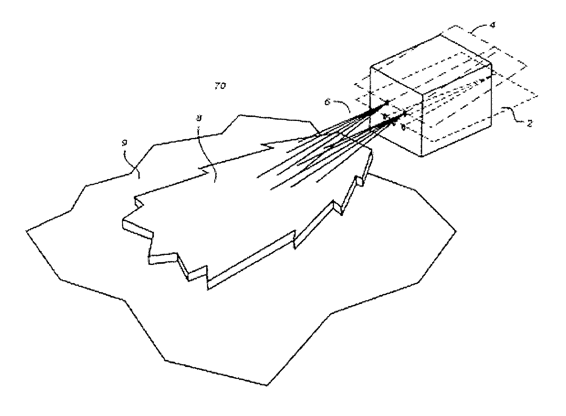
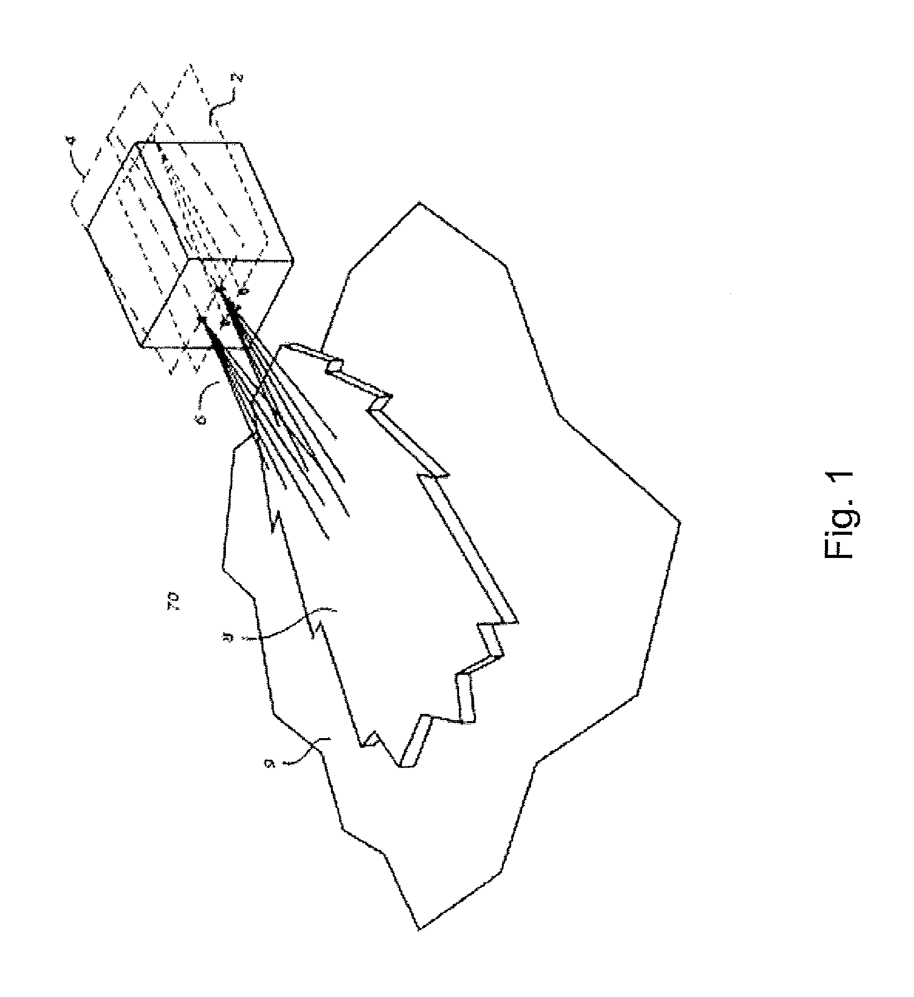
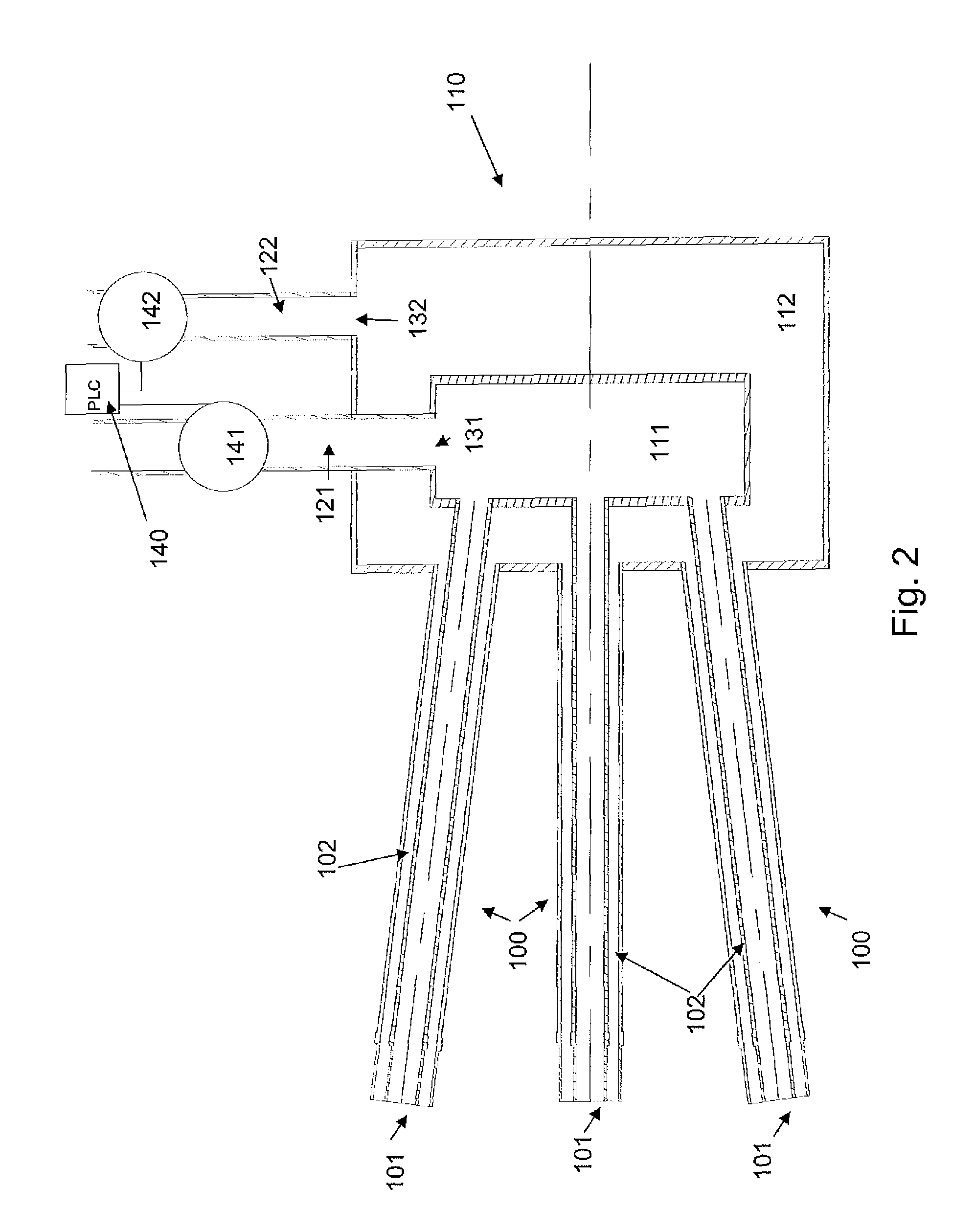
[0152]FIG. 2 is a schematic cross section across the fuel gas canals (plane 2) of the burner assembly of FIG. 1, in which a first fuel gas stream is supplied to the first fuel gas chamber and a second fuel gas stream is supplied to the second fuel gas chamber,

[0153]As shown in FIG. 2, each of the three (3) fuel gas canals 100 comprise an inner fuel-conducting passage 101 forming an inner fuel gas outlet and a coaxial outer fuel-conducting passage 102 forming an outer fuel gas outlet.

[0154]The three fuel gas canals 100 are in fluid connection with the fuel gas distributor 110. The fuel gas distributor comprises a first fuel gas chamber 111 and a second fuel gas chamber 112. The means for supplying fuel gas to the fuel gas distributor comprises (1) a first supply line is supplied with fuel gas by means comprising a first supply line 121 which supplies a first fuel gas to the first fuel gas chamber 111 via first inlet 131 and (2) a second supply line 122 which supplies a second fuel ga...

second embodiment

[0161]FIG. 3 represents is a schematic cross section across the fuel gas canals of the burner assembly of FIG. 1, in which the fuel gas stream supplied to the fuel gas distributor is split into a first fuel gas stream which is fed to the first chamber and a second fuel gas stream which is fed to the second fuel gas chamber,

[0162]As shown in FIG. 3, the means for supplying fuel gas to the fuel gas distributor comprises a supply line 120. Flow controller 150 controls the flow of fuel gas from a fuel gas source (not shown) to the fuel gas distributor 110 via supply line 120. Downstream of flow controller 150, supply line 120 is split into (1) a first supply branch which supplies fuel gas to the first fuel gas chamber 111 via first inlet 131 and (2) a second supply branch 122 which supplies fuel gas to the second fuel gas chamber 112 via second inlet 132. Valve 162, which in the illustrated embodiment is mounted on the second supply branch controls the portion of the fuel gas supplied b...


PUM


Abstract

Variable momentum burner assembly for separately injecting fuel gas and oxidant in a combustion zone, comprising at least two fuel gas canals, at least one oxidant canal and a fuel gas distributor, whereby the at least two fuel gas canals comprise an inner fuel-conducting passage forming an inner fuel gas outlet and an outer fuel-conducting passage forming an outer fuel gas outlet, said inner and said outer fuel-conducting passages being coaxially arranged; and whereby said fuel gas distributor comprises a first fuel gas chamber in fluid connexion with the inner fuel-conducting passage of the at least two fuel gas canals and a second fuel gas chamber in fluid connexion with the outer fuel-conducting passage of the at least two fuel gas canals.

Description

CROSS-REFERENCE TO RELATED APPLICATIONS[0001]This application is a §371 of International PCT Application PCT / EP2009 / 058293, filed Jul. 1, 2009, which claims §119(a) foreign priority to European Patent application 08305386.8, filed Jul. 8, 2008.BACKGROUND[0002]Field of the Invention[0003]The present invention relates to a combustion process and an apparatus therefor containing separate fuel and oxidant injectors to introduce fuel gas and oxidant separately in the combustion chamber of a furnace, so that the fuel burns with the oxidant in a wide luminous flame, and whereby the combustion of the fuel with the oxidant generates reduced quantities of nitrogen oxides (NOx).[0004]Related Art[0005]Industrial high temperature processes, such as glass or frit melting, ferrous and non ferrous materials smelting, use large amounts of energy to transform a variety of raw materials into a hot product that is then cast, formed or otherwise disposed of in further stages of the industrial process. T...

Claims


Application Information

Patent Timeline
Patent Type & Authority Patents(United States)
IPC IPC(8): F23D14/22F23D14/84F23N1/00F23N1/02F23D14/32
CPCF23N1/02F23D14/22F23D14/32F23D14/84F23D91/02F23N1/007F23D2200/00F23N2037/08Y02E20/344F23N2237/08F23N1/00Y02E20/34
Inventor AMIRAT, MOHANDDUPERRAY, PASCALGRAND, BENOITMORTBERG, MAGNUSMULON, JACQUESPAUBEL, XAVIERTSIAVA, REMIKALCEVIC, ROBERT
Owner LAIR LIQUIDE SA POUR LETUDE & LEXPLOITATION DES PROCEDES GEORGES CLAUDE
Why Eureka
Try Eureka