Method to form semiconductor devices

Active Publication Date: 2017-02-14
UNITED MICROELECTRONICS CORP
View PDF4 Cites 3 Cited by
  • Summary
  • Abstract
  • Description
  • Claims
  • Application Information

AI Technical Summary

Benefits of technology

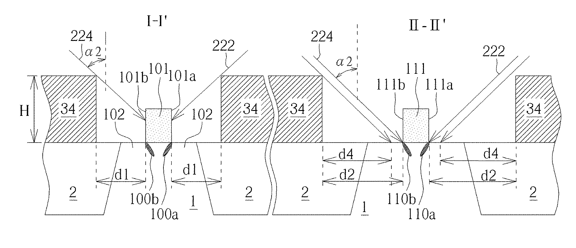
[0013]This invention provides a method to form different devices by utilizing the shadowing effect of the resist layer, enabling the selective implantation or blocking of ions into certain regions. Traditionally, efforts are made to minimize the shadowing effect of the resist layer during implantation process to obtain better implant uniformity across the s

Problems solved by technology

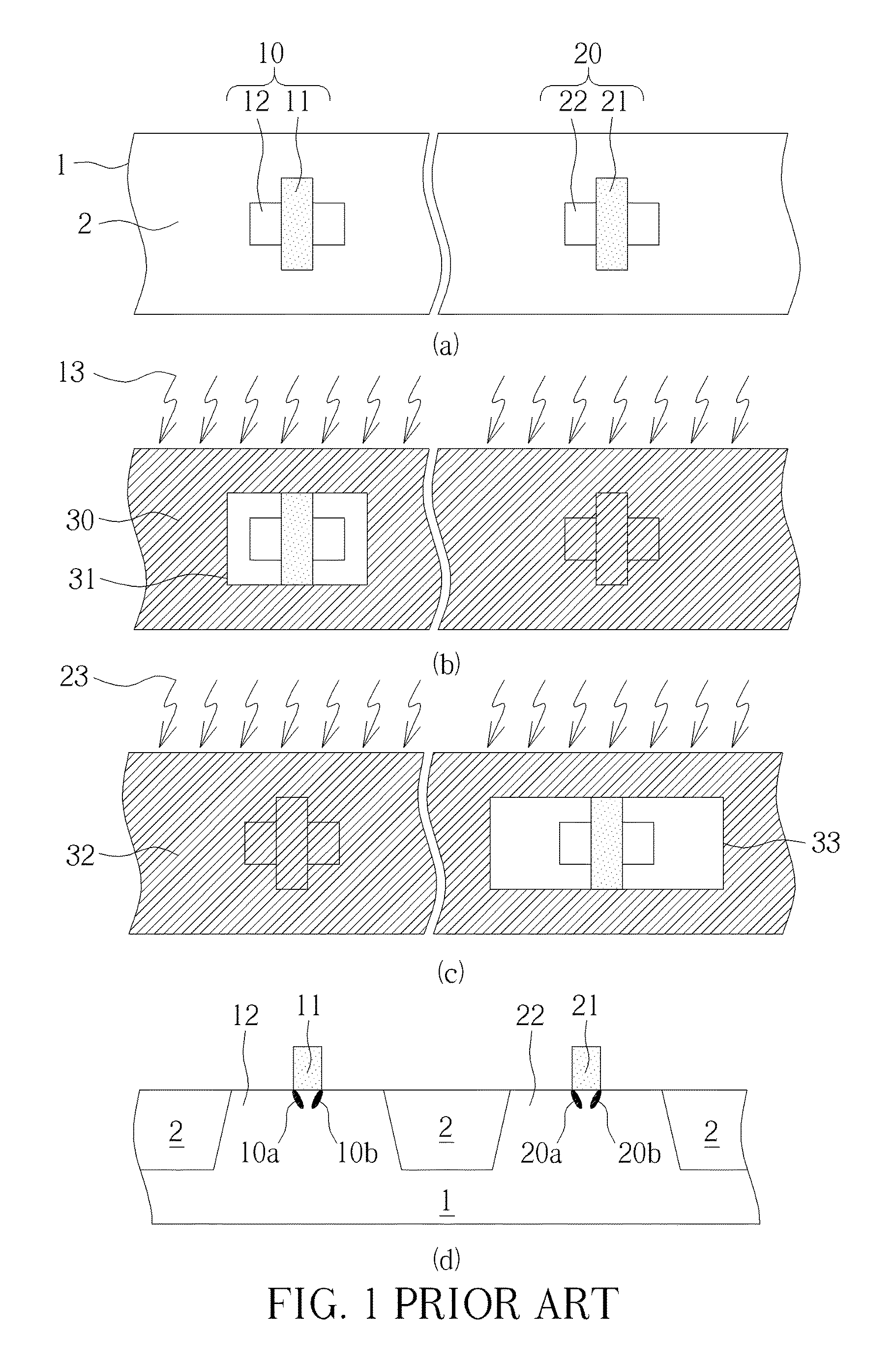
This phenomenon is referred to as “pocket shadowing” or “pocket blocking”, and usually results in undesirable deviations of the electrical characteristics of the transistor, such as a lower threshold voltage and a raised drive current which are not originally designed for the transistor.
As more and more devices are i

Method used


Image

  • Method to form semiconductor devices
  • Method to form semiconductor devices
  • Method to form semiconductor devices

Examples


Example

[0022]In the following detailed description, reference is made to the accompanying drawings which form a part hereof, and in which is shown, by way of illustration of specific embodiments in which the invention may be practiced. These embodiments are described in sufficient detail to enable those skilled in the art to practice the invention. Other embodiments may be utilized and that structural, logical and electrical changes may be made without departing from the spirit and scope of the present invention. The following detailed description is, therefore, not to be taken in a limiting sense, and the scope of the present invention is defined by the appended claims, along with the full scope of equivalents to which such claims are entitled.

[0023]One or more implementations of the present invention will now be described with reference to the attached drawings, wherein like reference numerals are used to refer to like elements throughout, and wherein the illustrated structures are not n...


PUM


Abstract

A method of forming semiconductor devices. First, a substrate is provided, and a first implant area and a second implant area are defined in a mask pattern. Subsequently, a resist layer on the substrate is patterned using the mask pattern to form a first opening exposing the first implant area and a second opening to expose the second implant area. After that, an ion implantation process including a partial shadowing ion implant is processed, wherein the second implant area is implanted by the partial shadowing ion implant to a predetermined concentration, and the first implant area is substantially not implanted by the partial shadowing ion implant.

Description

BACKGROUND OF THE INVENTION[0001]1. Field of the Invention[0002]The invention generally related to a method to manufacture semiconductors devices. More particularly, the invention related to a method to form semiconductor devices with reduced process steps.[0003]2. Description of the Prior Art[0004]As the functions of a semiconductor chip become more and more complicated, it usually comprises a variety of devices with different electrical characteristics.[0005]The threshold voltage (Vt) represents the switching characteristic of a transistor, and it is crucial for the magnitude of drive current and off-state leakage current. Generally, devices may be classified according to their threshold voltage. For example, devices of the same type, such as MOS transistors having the same geometry but different threshold voltages, may be classified into low threshold voltage devices (LVT), regular threshold voltage devices (RVT) and high threshold voltage devices (HVT). It is a sophisticated tas...

Claims


Application Information

Patent Timeline
IPC IPC(8): H01L21/338H01L21/266H01L27/11H01L21/027H01L21/265
CPCH01L27/1116H01L21/266H01L21/0273H01L21/26513H01L21/26586H01L27/1104H01L29/66492H01L29/1045H01L29/1083H01L21/823412H10B10/18H10B10/12H01L21/823807
Inventor HSIAO, SHIH-YINYANG, CHING-CHUNGCHENG, TUN-JEN
Owner UNITED MICROELECTRONICS CORP
Why Eureka
Try Eureka