Flexible intramedullary nail

a flexible, intramedullary technology, applied in the direction of ligaments, osteosynthesis devices, muscles, etc., can solve the problems of adding bone fractures, increasing the erosion of the cortex or insertion difficulty, and preventing unwanted penetration

Active Publication Date: 2017-02-28
FLEX TECH
View PDF12 Cites 1 Cited by
  • Summary
  • Abstract
  • Description
  • Claims
  • Application Information

AI Technical Summary

Benefits of technology

[0010]The disclosed nail is flexible to follow the natural curvature of a bone thereby preventing unwanted penetration, increased erosion of the cortex or insertion difficulties. Because of the difference in curvature between the natural bone and the intramedullary nail, insertion of the nail can become very difficult, preventing complete insertion of the nail into the bone, and potentially causing additional fractures of the bone.
[0013]A flexible intramedullary nail is disclosed that is manufactured from a biocompatible rigid material and has a substantially cylindrical hollow body. The nail has a leading segment with an entry hole at a distal end and at least one securing means and a trailing segment having a trailing edge and an attachment mechanism. The body has at least one flexible center section, each having at least one slot to provide flexibility. In one embodiment the at least one slot follows a sinuous, serpentine path to form a plurality of interlocking teeth. The serpentine path can follow a helical path or a concentric path. The helical path of said at least one slot is about 0.25 to about 5 cycles per diameter length and the helical angle ranges from about 5 degrees to about 20 degrees The ratio of the amplitude of the path to the pitch of the slot is in the range from greater than 0.1 to about 0.8. The width of each slot between about 0.5% and about 5.0% of the diameter of said flexible nail. The at least one slot can alternatively follow a helical path. Each of the slots has a proximal end and a distal end, with the proximal end being spaced from the trailing segment and the distal end being spaced from the leading segment. When multiple slots are incorporated, the proximal end of a slot is spaced from a distal end of a subsequent slot. The first of the at least one flexible center section and a second of the at least one flexible center section can be separated by a non-slotted section.
[0015]Each of the at least one slot can have a varied flexibility in relationship to another of slot from the group comprising increased flexibility, decreased flexibility, equal flexibility. Each of the slots can have sufficient width to form an unbound joint permitting limited movement in any direction upon application of tensile, compressive, and / or torsion forces. Alternatively, each slot can have an increased width in a first direction compared to a second direction to provide increased flexibility in said first direction. The varied flexibility can be achieved by varying the pitch of the helical slot and helix angle, said helical angle being in the range of about 10 degrees to about 45 degrees. The flexibility can also be achieved by varying the width of the helical slot.
[0021]This invention of a flexible intramedullary fixation device was first proposed and submitted to the National Institutes of Health as a Small Business Innovation Research proposal “Retrograde Femoral Reconstruction Fixation System” on Aug. 14, 1997 and assigned Application Number 1R43 AR45345-01. A revised application, #1R43 AR45345-01A1 was resubmitted on Apr. 14, 1998. The applications describe a flexible intramedullary nail that is inserted into the medullary canal of a long bone to align and stabilize the fracture by providing proximal and distal locking.
[0024]A plurality of slots can be employed thereby increasing the flexibility of the component, relative to a shaft having a single slot of identical pattern. The serpentine or sinuous path forms a plurality of teeth and complimentary recesses on opposite sides of the slot. The slot has sufficient width to form an unbound joint permitting limited movement in any direction between the teeth and the recesses, thereby providing limited flexibility in all directions upon application of tensile, compressive, and / or torsion forces to said component. In a similar manner the slot can have increased width in one direction compared to another direction thus providing increased flexibility in one direction.
[0025]The flexible segment can have different degrees of flexibility along the length of said shaft. The varied flexibility can be achieved by having the pitch of the helical slot vary along the length of the shaft. The varied flexibility corresponds to the variation in the pitch of the helical slot. The helical path can have a helix angle in the range of about 10 degrees to about 45 degrees, and the helix angle can be varied along the length of the shaft to produce correspondingly varied flexibility. Alternatively, the width of the helical slot can vary along the length of the shaft to provide the varied flexibility. The rigidity of the flexible shaft can be achieved through the design of the slot pattern, thereby enabling the use of thinner walls than would otherwise be require to produce equivalent rigidity. In a preferred embodiment, the ratio of the amplitude of the path to the pitch of the slot is in the range from greater than 0.1 to about 0.8.

Problems solved by technology

Because of the difference in curvature between the natural bone and the intramedullary nail, insertion of the nail can become very difficult, preventing complete insertion of the nail into the bone, and potentially causing additional fractures of the bone.

Method used


Image

  • Flexible intramedullary nail
  • Flexible intramedullary nail
  • Flexible intramedullary nail

Examples


Embodiment Construction

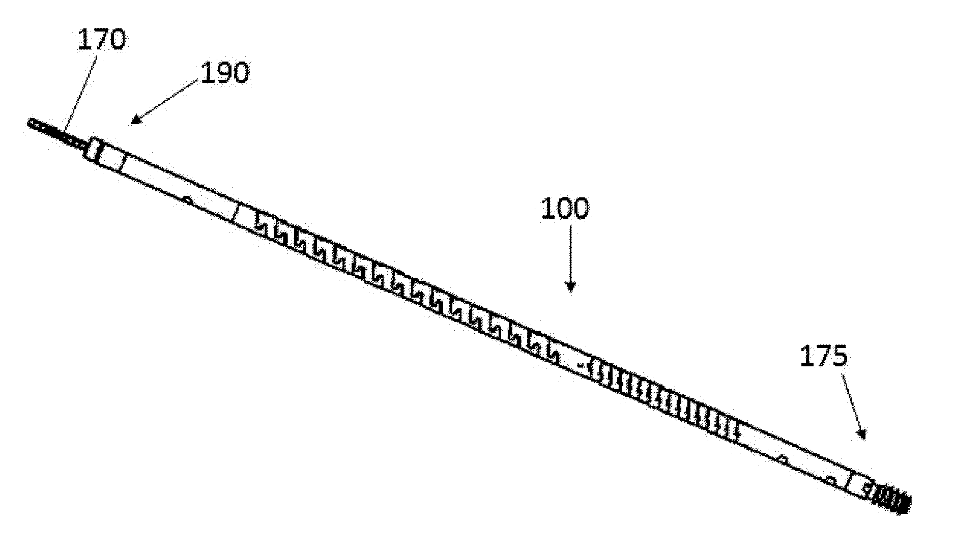
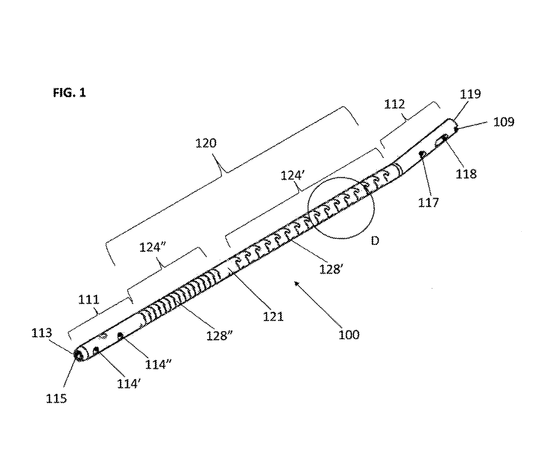
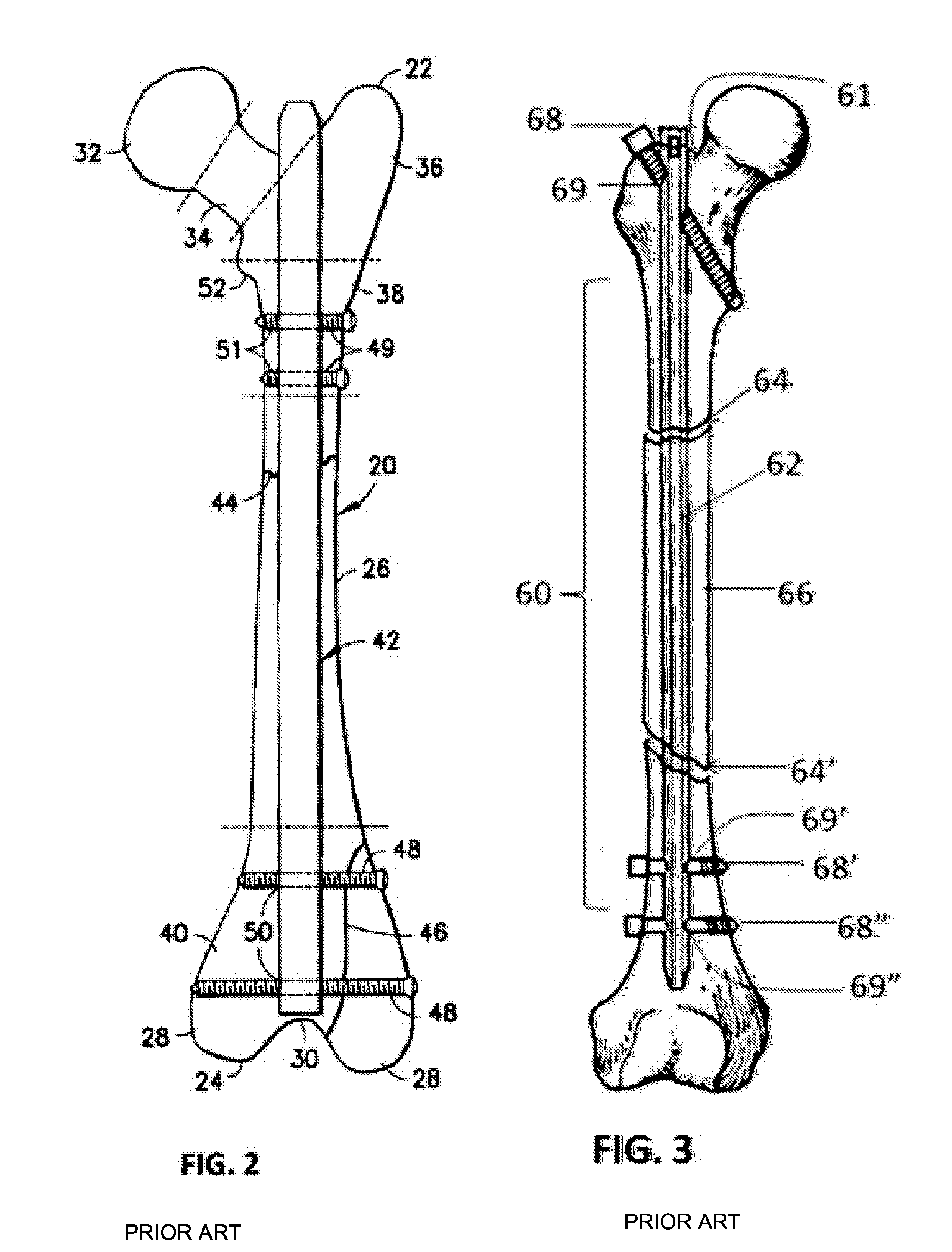
[0072]For the purposes herein the term “intramedullary rod”, also known as an “intramedullary nail” (IM nail), means a metal rod forced into the medullary cavity of a bone to align and stabilize fractures. IM rods are primarily inserted into the bone marrow canal in the center of the long bones of the extremities (e.g. femur, tibia, fibula, humerus, ulna and radius).

[0073]For the purposes herein the terms “slit” and “slot” are used interchangeably, consistent with their definitions, as follows:[0074]slot n. 1. A narrow opening; a groove or slit: a slot for coins in a vending machine; a mail slot.[0075]2. A gap between a main and an auxiliary airfoil to provide space for airflow and facilitate the smooth passage of air over the wing.

[0076]For the purposes herein the term pitch as used herein is defined as:[0077]pitch-n.1. The distance traveled by a machine screw in one revolution.[0078]The distance between two corresponding points on adjacent screw threads or gear teeth. (American He...


PUM


Abstract

A flexible intramedullary nail is disclosed that is manufactured from a biocompatible rigid material and having a substantially cylindrical hollow body, a leading segment with an entry hole at a distal end and at least one securing means and a trailing segment having a trailing edge and an attachment mechanism. The body has at least one flexible center section, each having at least one slot to provide flexibility. In one embodiment the at least one slot follows a sinuous, serpentine path to form a plurality of interlocking teeth that can follow a helical or a concentric path. Each of the slots has a proximal end and a distal end, with the proximal end being spaced from the trailing segment and the distal end being spaced from the leading segment. When multiple slots are incorporated, the proximal end of a slot is spaced from a distal end of a subsequent slot. The first of the at least one flexible center section and a second of the at least one flexible center section can be separated by a non-slotted section. The nail can be used with a flexible insertion shaft or a locking shaft.

Description

FIELD OF THE INVENTION[0001]The present invention relates generally to the treatment of bone fractures and pertains, more specifically, to the fixation of fractures in long bones in the body.BACKGROUND OF THE INVENTION[0002]Long bones are those greatly elongated bones such as the femur or tibia that are found in a human or in an animal. When a long bone is fractured, the surgeon immobilizes the various bone segments relative to one another to promote healing of the fracture. The immobilization or fixation of the segments is accomplished by the use of one or more rigid devices that span the fracture site and are located either external to the body or internally on the bone surface or inside the bone canal.[0003]This invention of a flexible intramedullary fixation device was first proposed and submitted to the National Institutes of Health as a Small Business Innovation Research proposal “Retrograde Femoral Reconstruction Fixation System” on Aug. 14, 1997 and assigned Application Numb...

Claims


Application Information

Patent Timeline
Patent Type & Authority Patents(United States)
IPC IPC(8): A61B17/04A61B17/84A61B17/86A61F2/08A61B17/72
CPCA61B17/7233A61B17/869A61B17/8625A61B17/864A61B17/8605A61B17/866A61B17/7208
Inventor KRAUSE, WILLIAM R.
Owner FLEX TECH
Why Eureka
Try Eureka