Multi-segmented tube sheet

a tube sheet, multi-segment technology, applied in the direction of evaporator regulation/control, cell components, separation processes, etc., to achieve the effect of improving the structure improving the rigidity of the tube sheet, and high toleran

Active Publication Date: 2017-02-28
NEPTUNE BENSON INC
View PDF47 Cites 14 Cited by
  • Summary
  • Abstract
  • Description
  • Claims
  • Application Information

AI Technical Summary

Benefits of technology

[0014]For the present invention the same end-use tube sheet in this arrangement will take a fraction of the time to manufacture, due primarily to the substantially reduced thickness of individual sheets, if punched on an automated press, burned with a laser or a plasma cutter, or printed using additive manufacturing technologies [ie 3D printing as but one example] and assembled and fixed. An added feature in accordance with the present invention is that layering of the tube sheet allows interstitial placement of materials creating a non-homogeneous device that in its entirety functions both as a tube sheet as well as a multifunctional filtration device or membrane. Fixing the thin sheets into contact serves the purpose of maintaining the bulkhead effect and the structural integrity, as well as the desired tube spacing. One or more fasteners are used to secure all layers or sheets together as a unitary mass functioning as a tube sheet. By “fasteners” reference can be made to any one of a number of devices or techniques by which the individual layers or sheets are secured together.

Problems solved by technology

This is a risky endeavor because the precise location of the TXV bulb 27 is not assured, nor is there perfect conduction of the temperature or consideration for the manufacturing tolerances of the multitude of devices that have to work in concert to cause the valve actuation to control the flow at valve 24, which ultimately determines the volume of heat transfer fluid available to change the temperature of the fluid transiting the tube side of the heat exchanger.

Method used


Image

  • Multi-segmented tube sheet
  • Multi-segmented tube sheet
  • Multi-segmented tube sheet

Examples


Embodiment Construction

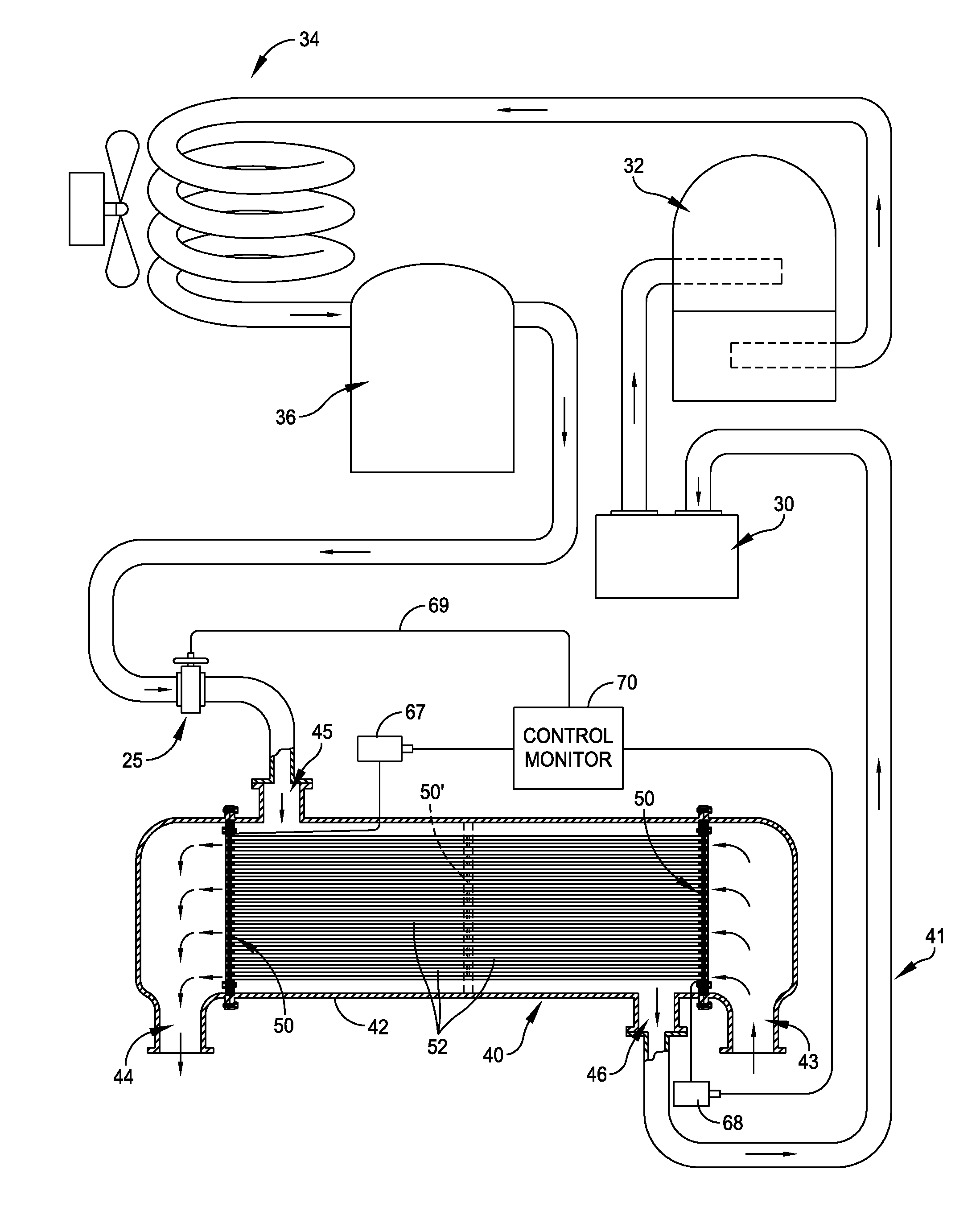
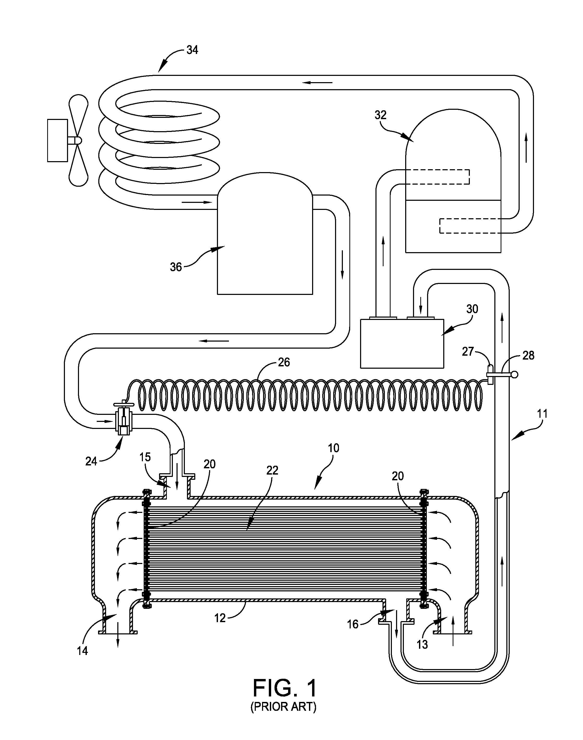
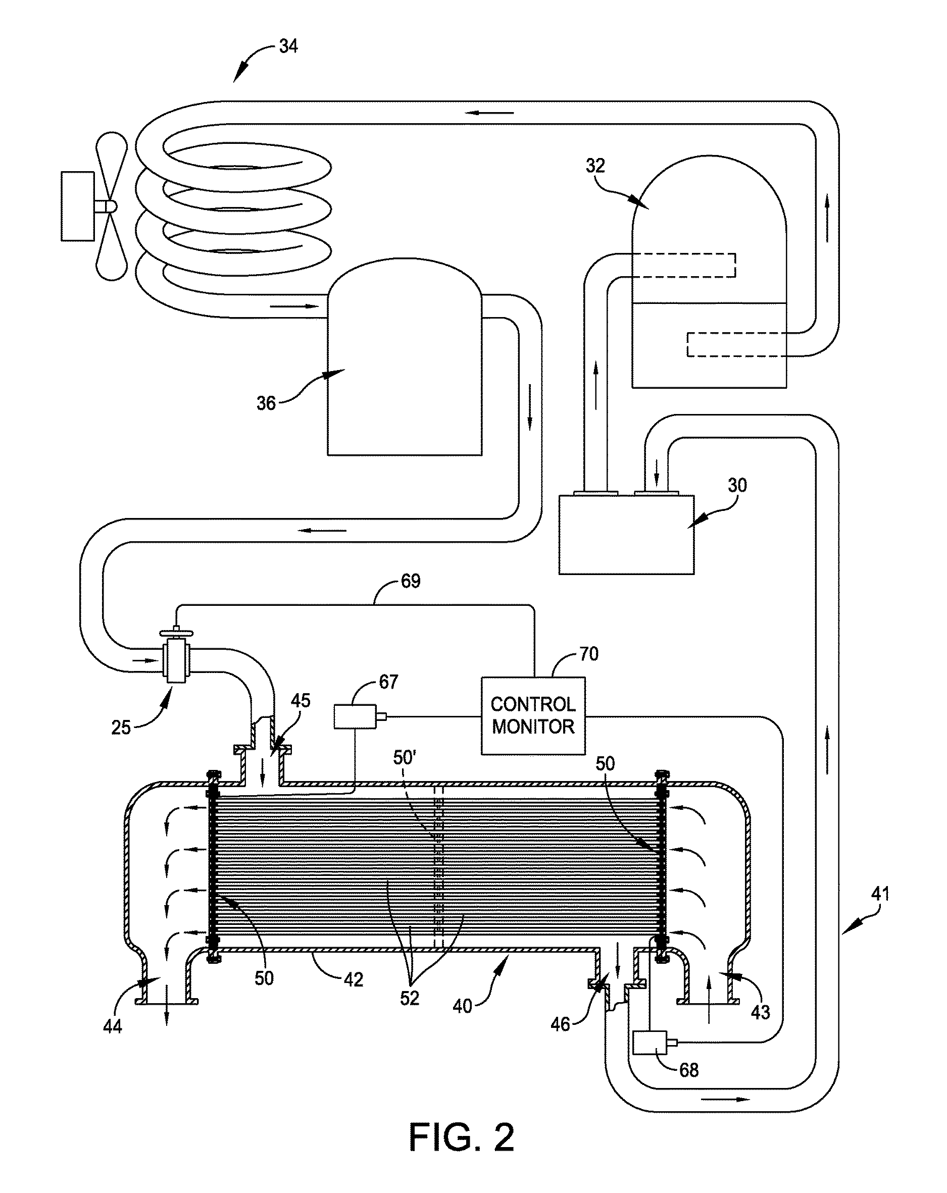
[0042]As mentioned before, in accordance with the present invention the tube sheet is constructed out of multiple thinner layers of sheet material that are aligned to each other and to the tubes in the assembly process, and then fixing this assembly together to achieve the final structural integrity and bulkhead characteristics of a tube sheet. In the drawings of U.S. Pat. No. 9,149,742 which issued on Oct. 6, 2015 which is hereby incorporated by reference herein in its entirety, several different versions of tube sheet constructions are set forth such as in FIGS. 1-4, along with a diagram in FIG. 5 which is an illustration of the application of the principles of the present invention to a filtration structure.

[0043]In accordance with one aspect of the present invention there is provided a method of manufacturing a tube sheet by forming a plurality of separate thin tube sheet segments such as shown in FIG. 7 as layers or sheets 1-6. The next step is forming multiple holes in each sh...


PUM

PropertyMeasurementUnit
diameteraaaaaaaaaa
diameteraaaaaaaaaa
diameteraaaaaaaaaa

Abstract

A heat exchanger that is constructed with a heat exchanger shell having inlet and outlet plenums and fluid inlet and outlet ports, and a tube sheet construction disposed in the heat exchanger shell. The tube sheet construction includes at least two separate tube sheets and a plurality of tubes that extend between the separate tube sheets. Each tube sheet includes at least two planar tube sheet segments and a interstitial layer disposed between the at least two tube sheet segments, and at least one sensor element supported by each of the interstitial layers. A control monitor controls flow through the shell by a feedback control from the sensor to an inlet control valve and / or a stimulus device excites the media layer. In an alternate embodiment opposed position sensor elements may be provided at opposite sides of the tube sheet construction.

Description

RELATED CASES[0001]This application is a continuation-in-part (CIP) of U.S. Ser. No. 14 / 830,994 filed on Aug. 20, 2015 which is scheduled to issue as U.S. Pat. No. 9,303,924 on Apr. 5, 2016 which is a continuation-in-part (CIP) of U.S. Ser. No. 14 / 535,655 filed on Nov. 7, 2014 which is now U.S. Pat. No. 9,127,896 which issued on Sep. 8, 2015 and which claims priority to under 35 U.S.C. §119 (e) to commonly owned and U.S. Provisional Patent Application No. 62 / 063,681 which was filed on Oct. 14, 2014, and which is incorporated by reference herein in its entirety. Reference is also made to co-pending application Ser. No. 14 / 535,596 filed on Nov. 7, 2014 now U.S. Pat. No. 9,149,742 which issued on Oct. 6, 2015, and a co-pending continuation-in-part (CIP) application U.S. Ser. No. 14 / 830,956 filed on Aug. 20, 2015 and which is set to issue as U.S. Pat. No. 9,302,205 on Apr. 5, 2016. All of the above identified applications are incorporated by reference herein in their entirety.FIELD OF T...

Claims


Application Information

Patent Timeline
Patent Type & Authority Patents(United States)
IPC IPC(8): B01D1/00F28D7/16F28F9/02H01M2/00F28F1/00F28F9/007B01D29/50B01D29/56F28D9/00F28F3/12F28F21/08F28F27/00A61F7/00B01D5/00
CPCF28F3/12A61F7/00B01D1/00B01D1/0082B01D5/00F28D7/16F28D9/0031F28F1/00F28F9/007F28F9/0229F28F9/0275F28F21/082F28F21/087F28F27/00H01M2/00F28F2200/00F28F2210/10F28F2275/20F28F2275/205F28F9/0131F28F9/0221F28F21/08F28F2265/12Y02E60/10H01M50/00
Inventor NEHLEN, III, PAUL F.
Owner NEPTUNE BENSON INC
Why Eureka
Try Eureka