Agricultural planter with automatic depth and seeding rate control

a planter and automatic technology, applied in agricultural machines, applications, instruments, etc., can solve the problems of inability to collect enough measurements to produce a spatially accurate map of soil moisture, inability to use fixed moisture sensors to link soil moisture with soil properties, and inability to capture spatial variability

Active Publication Date: 2017-03-07
VERIS TECH
View PDF3 Cites 44 Cited by
  • Summary
  • Abstract
  • Description
  • Claims
  • Application Information

AI Technical Summary

Benefits of technology

[0013]A method and system for measuring multiple soil properties on-the-go is provided on an implement for traversing a field. An optical module is carried by the implement for collecting soil reflectance data. A pair of soil contact blades protrude from or are embedded in the optical module for collecting soil EC data and soil moisture data. A switching circuit or phase lock loop allows the same soil contact blades to feed signals to both a soil EC signal conditioning circuit and a soil moisture signal conditioning circuit. The soil moisture data can be used to calibrate the soil EC data and the soil reflectance data to compensate for effects of changing soil moisture conditions across a field. The system can also be used on a planter to control planting depth and / or seeding rate in real time based on multiple soil properties collected during planting.

Problems solved by technology

However, these moisture sensors do not capture the spatial variability as their expense and manual deployment make it unfeasible to collect enough measurements to produce a spatially accurate map of soil moisture.
However, the use of fixed moisture sensors does not link soil moisture with soil properties that affect water-holding capacity and crop usage of water.
Soil EC and soil color sensors have been developed and are being used to relate to soil texture and organic matter, but no system or method exists for accounting for the contribution of soil moisture.

Method used


Image

  • Agricultural planter with automatic depth and seeding rate control
  • Agricultural planter with automatic depth and seeding rate control
  • Agricultural planter with automatic depth and seeding rate control

Examples


Embodiment Construction

[0032]A method and system for measuring multiple soil properties according to the present invention will now be described in detail with reference to FIGS. 1 to 12 of the accompanying drawings.

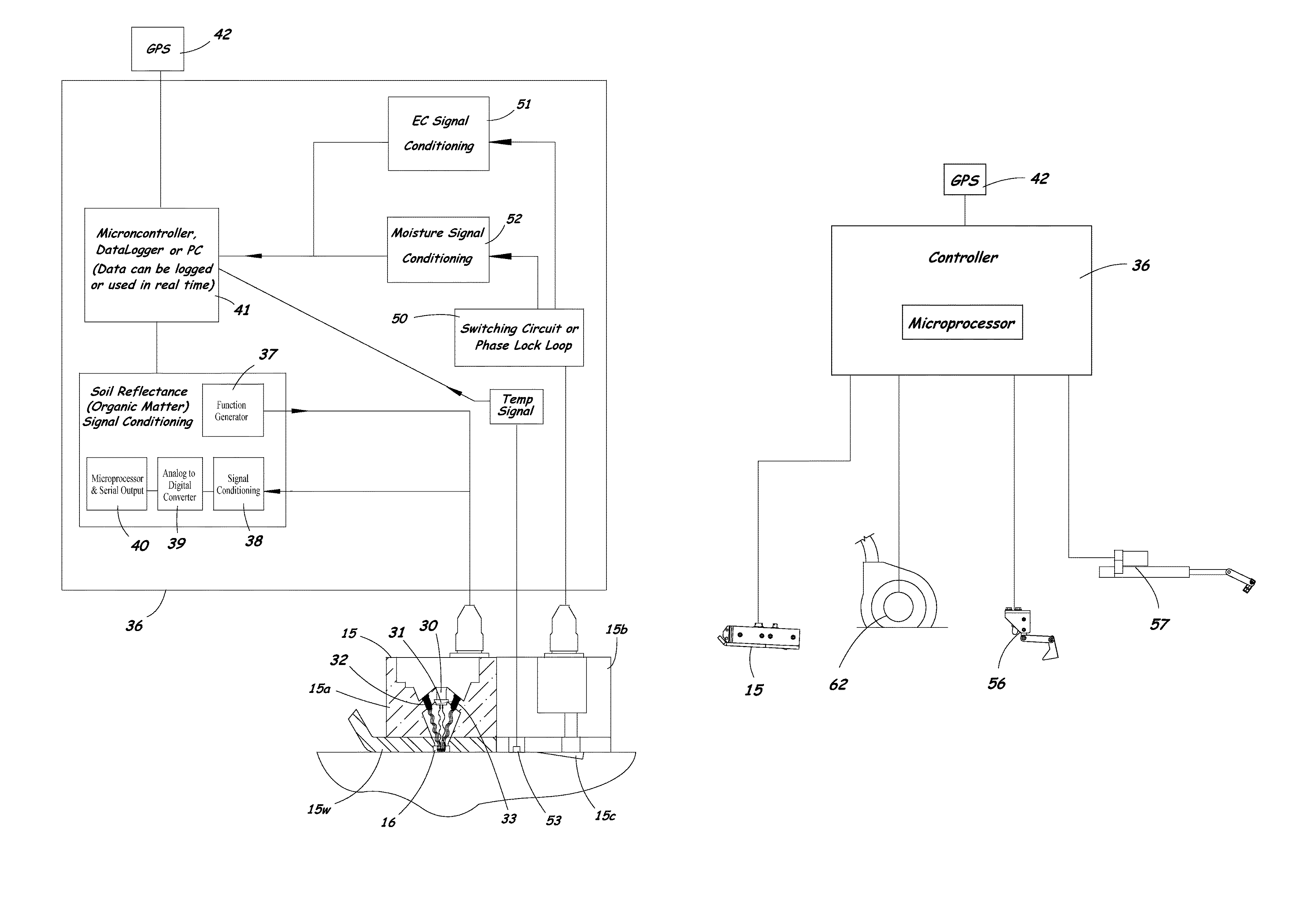
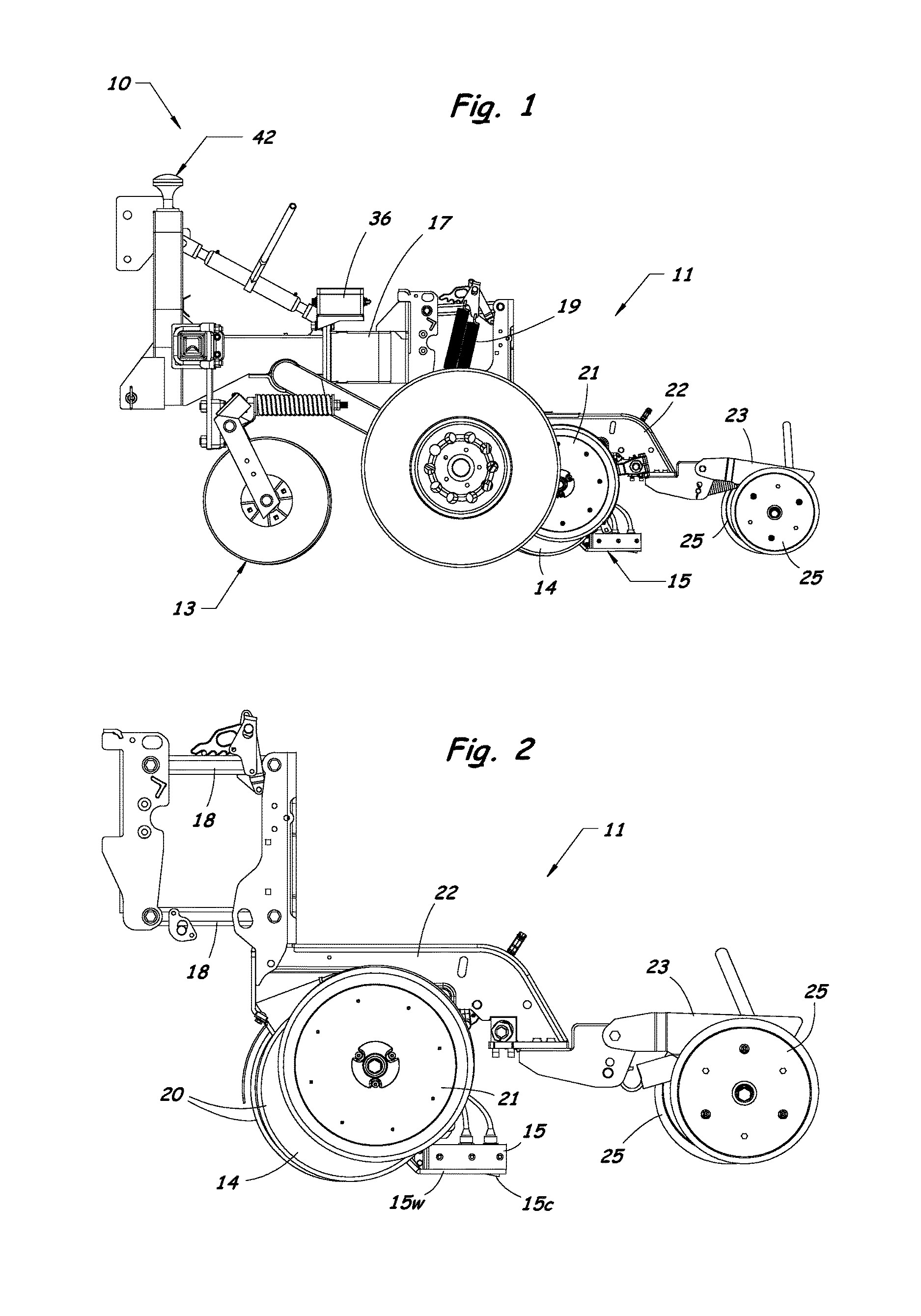
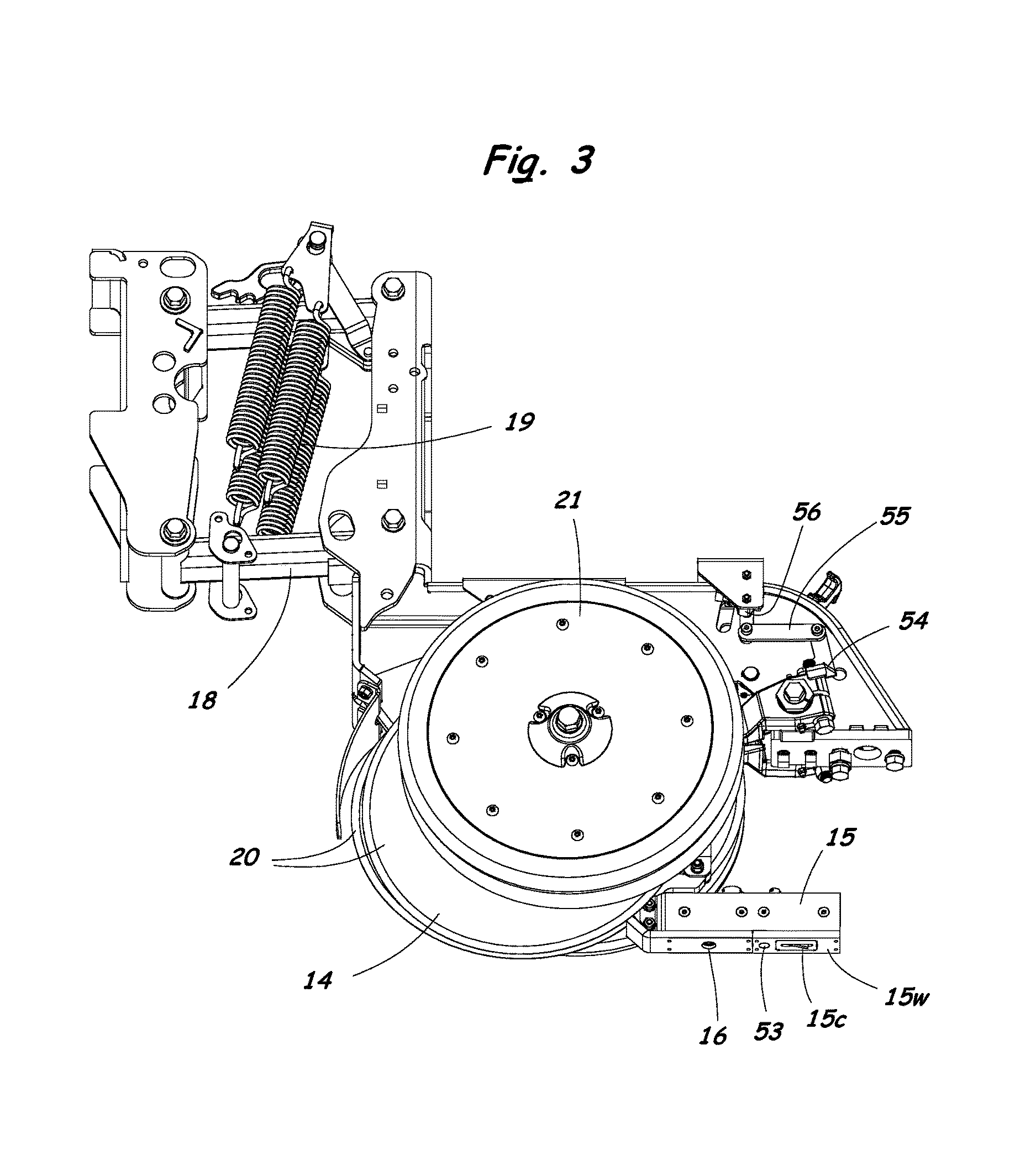
[0033]FIGS. 1 to 3 illustrate an implement 10 having a specially configured row unit 11 for measuring multiple soil properties according to the present invention. The implement 10 includes a coulter 13 for cutting through residue and for opening a slot in the soil. The row unit 11 includes a furrow opener assembly 14 that creates a furrow in the soil, and a sensor module 15 containing sensors for measuring multiple soil properties. The row unit 11 can be mounted to a toolbar 17 of the implement 10 by a parallel linkage 18 that allows the furrow opener 14 and sensor module 15 to follow ground undulations while maintaining a consistent depth in the soil. A plurality of springs 19 or a pneumatic system (not shown) can be used to provide an adjustable down-force to match soil conditions.

[0034]The ...


PUM


Abstract

An agricultural planter having sensors for measuring multiple soil properties adjusts planting depth and seeding rate in real time based on the measured soil properties. An optical module is carried by the planter for collecting soil reflectance data. A pair of soil contact blades protrude from or are embedded in the optical module for collecting soil EC data and soil moisture data. A switching circuit or phase lock loop allows the same soil contact blades to feed signals to both a soil EC signal conditioning circuit and a soil moisture signal conditioning circuit. The soil moisture data can be used to calibrate the soil EC data and the soil reflectance data to compensate for effects of changing soil moisture conditions across a field. The sensor module can be positioned behind a seed tube and used as a seed firmer, or incorporated into a seed tube guard.

Description

RELATED APPLICATIONS[0001]This application claims the benefit of U.S. Provisional Patent Application No. 61 / 812,131 filed on Apr. 15, 2013. The entire content of the priority application is incorporated herein by reference.BACKGROUND OF THE INVENTION[0002]Field of the Invention[0003]The present invention relates generally to methods and systems for measuring multiple soil properties across a field, and to agricultural planters that vary seeding rates and planting depths on-the-go during planting operations.[0004]Description of the Related Art[0005]Soil moisture is a major driver of crop production, particularly in arid regions. Soil moisture varies spatially within fields due to soil texture, topography, crop usage, irrigation patterns, and various other variables.[0006]Fixed, semi-permanent moisture sensors (e.g., gypsum blocks and neutron probes) and manually inserted sensors (e.g., TDR, capacitance) have been used for many years to monitor soil moisture levels in agricultural fie...

Claims


Application Information

Patent Timeline
Patent Type & Authority Patents(United States)
IPC IPC(8): A01C5/06A01C7/10A01C7/20A01B49/06A01B63/00A01B49/04
CPCA01C5/064A01C7/203A01C7/102A01B49/06A01B49/04A01B63/008A01C5/06A01C5/068A01C21/00G01N33/24G01N2033/245G01N21/55G01N27/223G01N2021/1738
Inventor LUND, ERICMAXTON, CHASEJENSEN, KYLE
Owner VERIS TECH
Why Eureka
Try Eureka