Anhydrous ammonia fertilizer distribution line monitor

a technology of anhydrous ammonia and monitoring equipment, which is applied in the direction of liquid fertiliser regulation systems, direct liquid fertiliser delivery, agriculture, etc., can solve the problems of reducing crop yield, reducing the yield of crops, and reducing the cost of fertilizer, so as to reduce grain yield and the effect of fertilizer cos

Inactive Publication Date: 2017-03-14
HINIKER
View PDF4 Cites 1 Cited by
  • Summary
  • Abstract
  • Description
  • Claims
  • Application Information

AI Technical Summary

Benefits of technology

[0018]One or more anhydrous ammonia distribution manifolds are employed on each anhydrous ammonia fertilizer distributor. A distribution line is attached to a manifold discharge port and to an injector knife. The number of injector knives employed on each fertilizer applicator has increased. Multiple factors have caused the increase in the number of fertilizer distributor knives employed on each applicator. Primary factors include a reduction of soil compaction, a decrease in the availability of competent operators and the economic factors that require each acre of land to produce more food at a lower cost.
[0038]The cost of anhydrous ammonia fertilizer and the desire to control the quantity of fertilizer applied is mentioned above. However, the cost of fertilizer is minor compared to the decreased yield of grain in one row of plants that can occur in a short period of time when a distribution line is damaged or severed.

Problems solved by technology

Excess nitrogen will reduce yield of crops such as corn.
Insufficient nitrogen will also reduce crop yield.
Injection of anhydrous ammonia into soil is subject to a number of problems.
Determining the quantity of nitrogen to be added is complicated by the fact that a substantial quantity of nitrogen may be stored in the soil.
The change in some anhydrous ammonia from a liquid to a vapor makes accurate control of the application rate difficult.
Vapor separated from the liquid results in the over application rate in some areas.
The separation of vapor may also result in the loss of some anhydrous ammonia.
However, a pump in the supply system between a nurse tank and liquid discharge nozzle will create a pressure drop on the pump inlet side.
Separation of the vapor generally results in a loss of some anhydrous ammonia.
The additional anhydrous ammonia from vapor may provide excess nitrogen to one crop row and may change crop yield in that crop row.
A number of additional distribution problems may occur.
Some of these problems are obvious to an operator without a sensor warning.
A plugged distribution line is however difficult to detect without a suitable monitor system.
However, if there is significant vapor mixed with the liquid, the distributor will not discharge equal quantities of fertilizer into each line.
Each of these devices may create a pressure drop.
The movements of the lines may decrease the size of the inside passage, wear a hole in a line or even sever a line.
The number of lines extending from each distributor to each of the knives and the small quantity of anhydrous ammonia passing through each line renders visual line monitoring difficult for an operator of an applicator.

Method used


Image

  • Anhydrous ammonia fertilizer distribution line monitor
  • Anhydrous ammonia fertilizer distribution line monitor
  • Anhydrous ammonia fertilizer distribution line monitor

Examples


Embodiment Construction

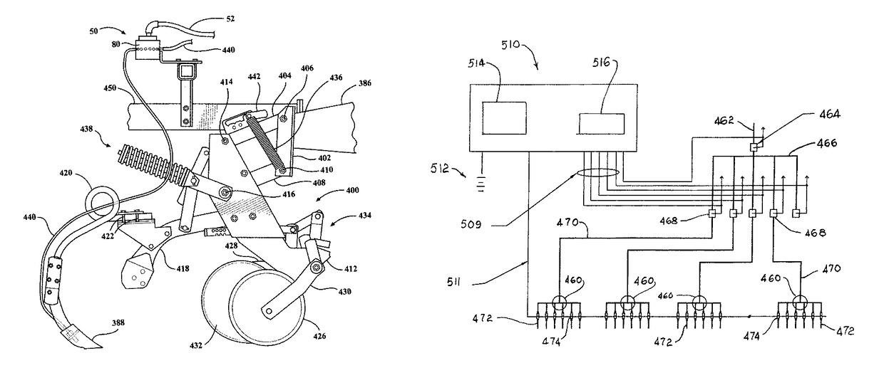
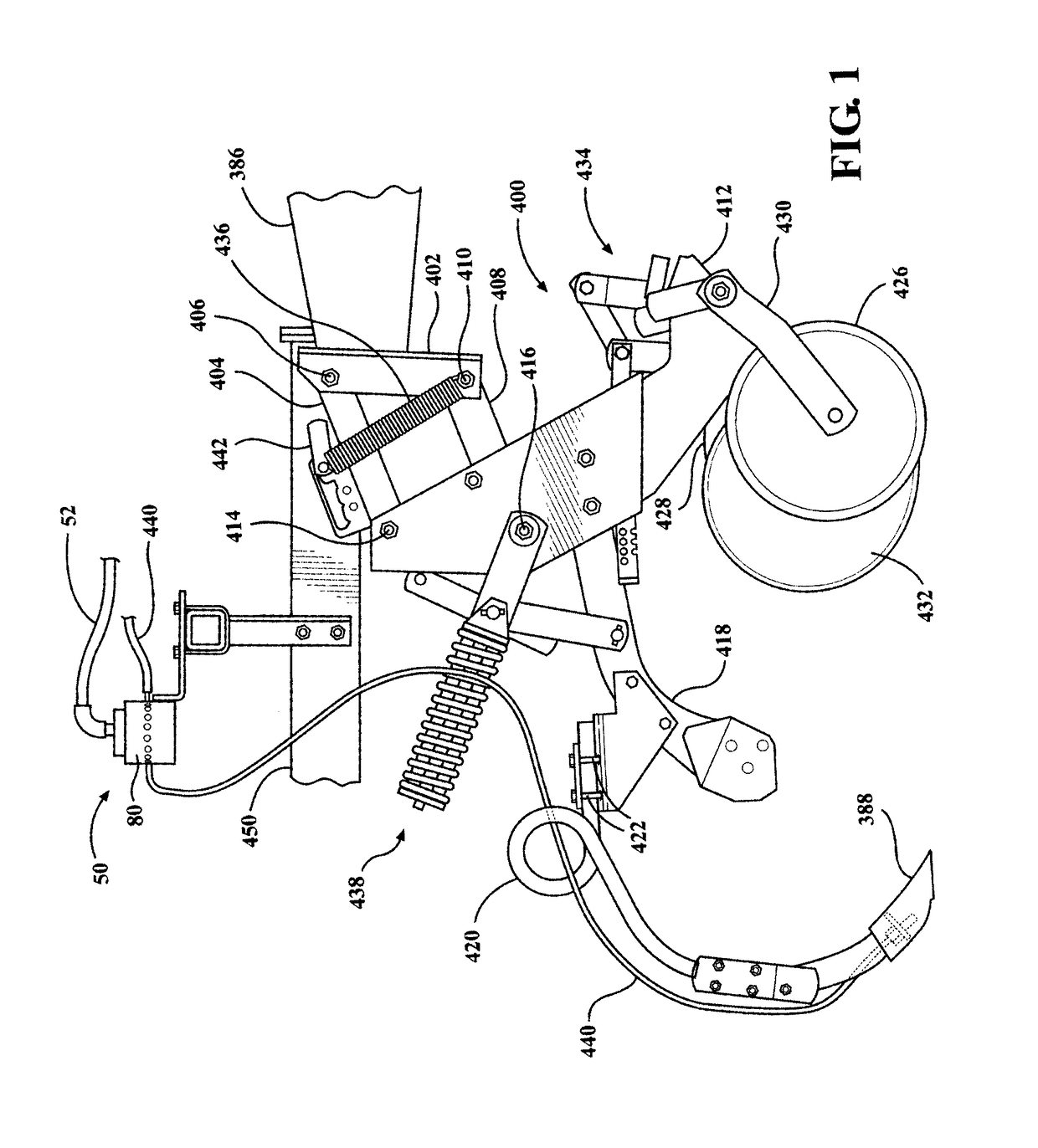
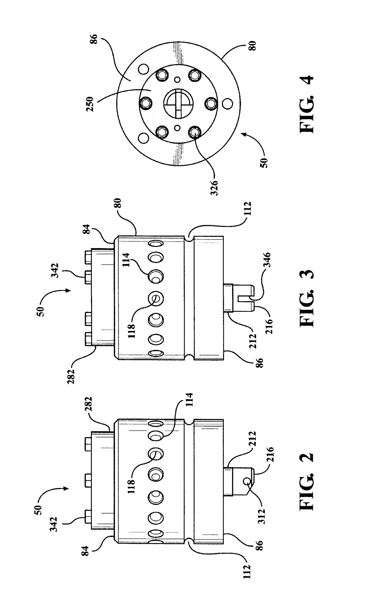
[0068]The anhydrous ammonia fertilizer distribution system 38 shown schematically in FIG. 20 includes a pressurized supply vessel 40, a heat exchanger 44, flow meter 46, an on and off valve 48 and a variable orifice distributor assembly 50. A supply line 42 carries anhydrous ammonia from the supply vessel 40 to the heat exchanger 44. A continuing supply line 52 carries anhydrous ammonia from the heat exchanger to the variable orifice distributor 50 through the flow meter 46 and the on and off valve 48. The supply vessel 40 is pressurized by the vapor pressure of the anhydrous ammonia at the temperature of the liquid in the vessel. The vapor pressure in the supply vessel is generally between fifty pounds per square inch and one hundred and fifty pounds per square inch depending upon the temperature. At eighty degrees Fahrenheit the vapor pressure is one hundred and thirty eight pounds per square inch. The heat exchanger 44 cools the anhydrous ammonia to a temperature at which the vap...


PUM


Abstract

The monitor system for an anhydrous ammonia fertilizer injection system includes a manifold with a plurality of discharge lines connected to soil engaging knives. A temperature sensor is mounted in each discharge line. The temperature of fertilizer in each discharge line is measures and transmitted to a microprocessor in a console. The temperature in a discharge line is compared with the average temperature in the other discharge lines. This comparison is made for each discharge line connected to a manifold to determine the temperature variations. The variations are compared to a temperature variation number provided by the operator. If an excessive variation occurs a warning is provided. A console screen graph shows which discharge line needs inspection.

Description

TECHNICAL FIELD[0001]The invention is a system for monitoring an anhydrous ammonia fertilizer applicator apparatus that includes a temperature sensor in each distribution line between a manifold and the associated injector knife, a monitoring console that receives temperature data from each distribution line, displays the temperature sensor data for the system operator to observe and provides an operator alert concerning a deviation in the temperature measured by one sensor relative to other sensors which exceeds an operator set deviation from the average of the temperatures in a number of the distribution lines at substantially the same time.BACKGROUND OF THE INVENTION[0002]Growing plants need nitrogen. Plants such as maize (Indian corn) require a substantial quantity of nitrogen. The soil corn plants grow in obtains nitrogen from legumes such as soybeans, from snow and from other sources. Excess nitrogen will reduce yield of crops such as corn. Insufficient nitrogen will also redu...

Claims


Application Information

Patent Timeline
Patent Type & Authority Patents(United States)
IPC IPC(8): A01C23/02A01C23/00
CPCA01C23/024A01C23/007A01C15/06G01K13/02
Inventor ARDISON, PAUL L.GRAMLING, DAVID
Owner HINIKER
Why Eureka
Try Eureka